
Powder composition

a technology of composition and powder metal, which is applied in the direction of lubricant composition, transportation and packaging, metal-working apparatus, etc., can solve the problems of rust formation in the die cavity, aqueous dispersions are a source of rust formation, and the thickness of the film within the die cavity has a tendency to vary, so as to achieve high and consistent densities

Inactive Publication Date: 2003-12-18
HOGANAS AB
View PDF5 Cites 2 Cited by
  • Summary
  • Abstract
  • Description
  • Claims
  • Application Information

AI Technical Summary

Benefits of technology

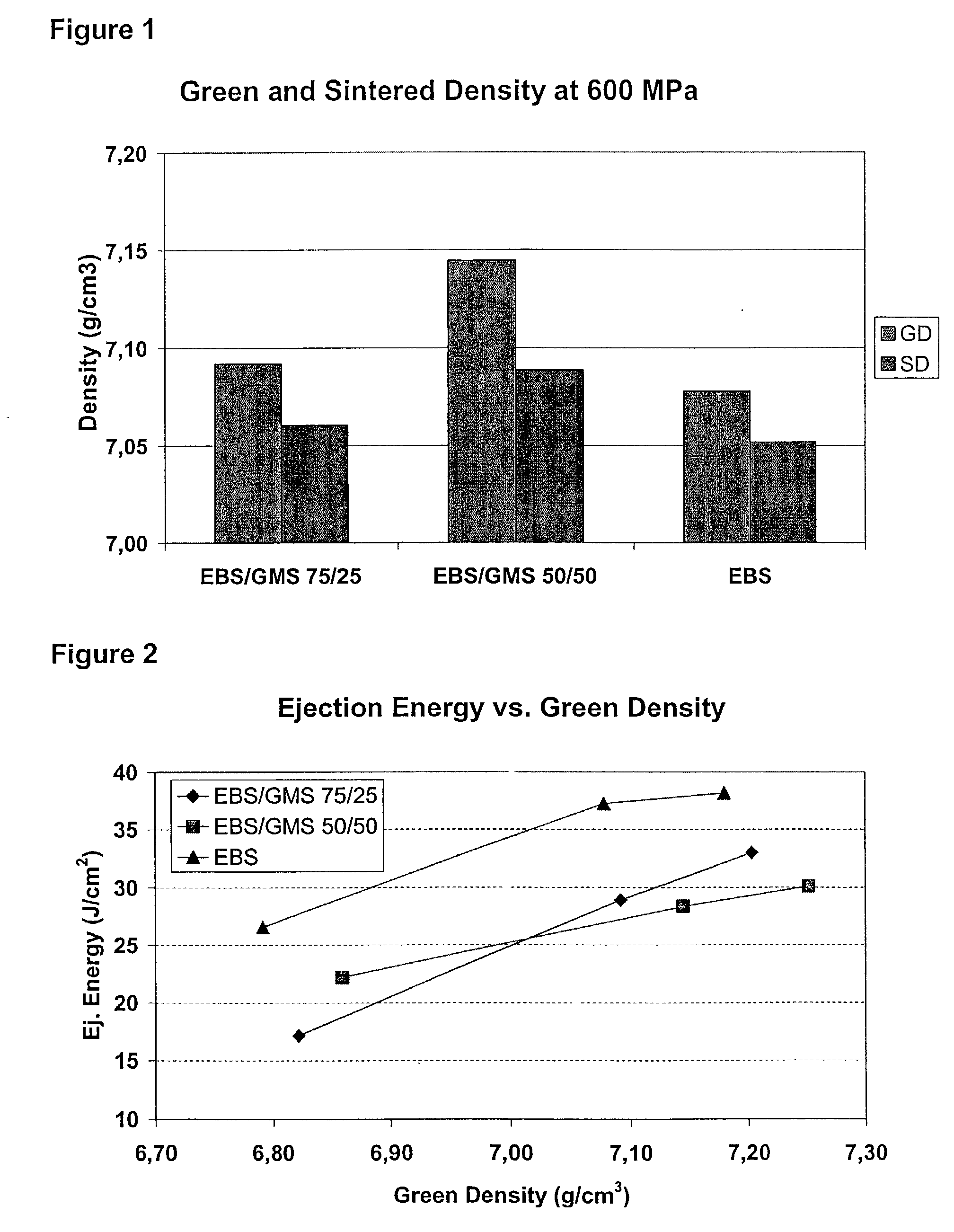
[0012] An object of the invention is to provide an iron-based powder metal composition comprising a lubricant resulting in compacts with high and consistent densities.
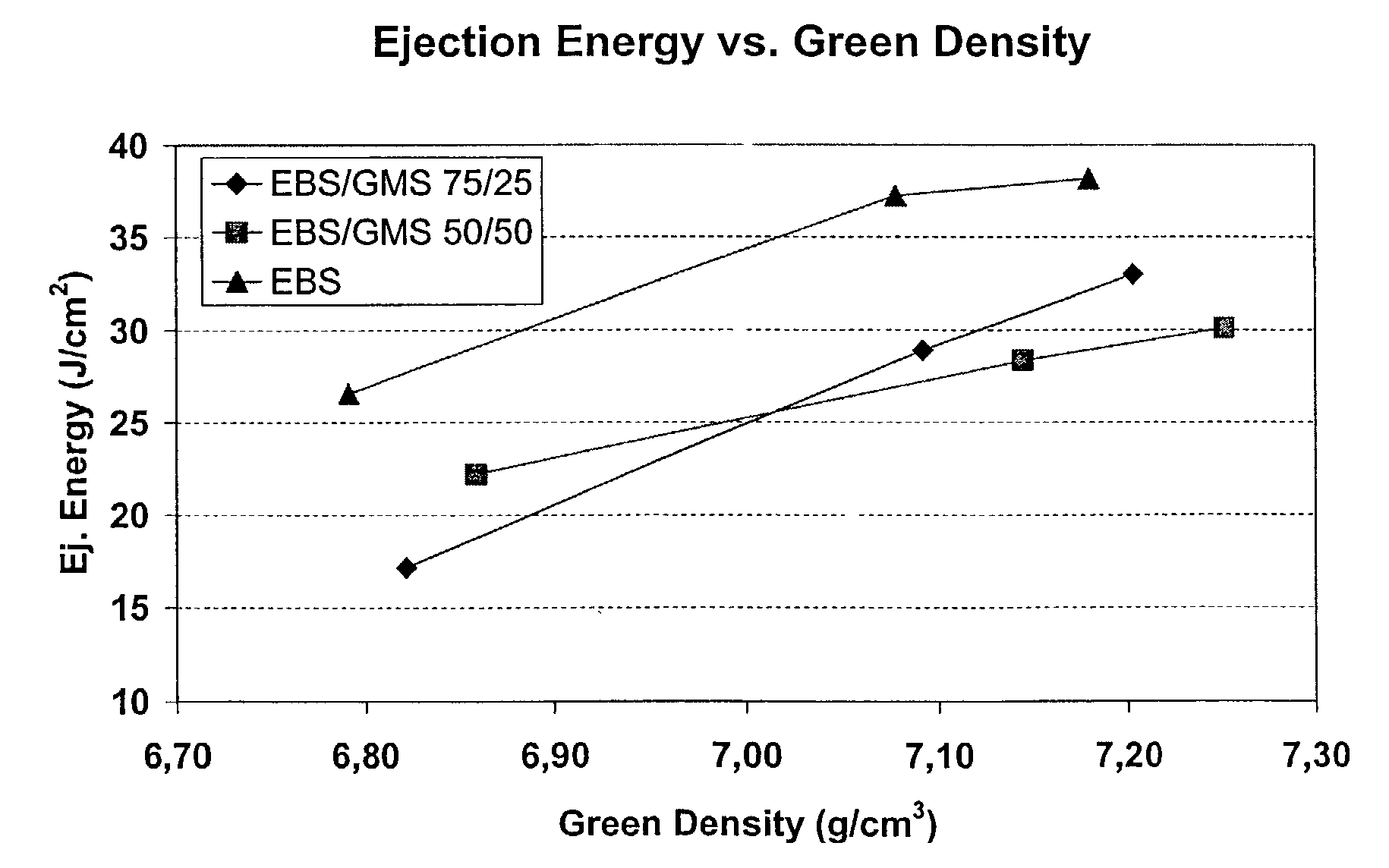
[0013] A second object of the invention is to provide an iron-based powder metal composition comprising a lubricant resulting in compacts requiring low ejection energies.
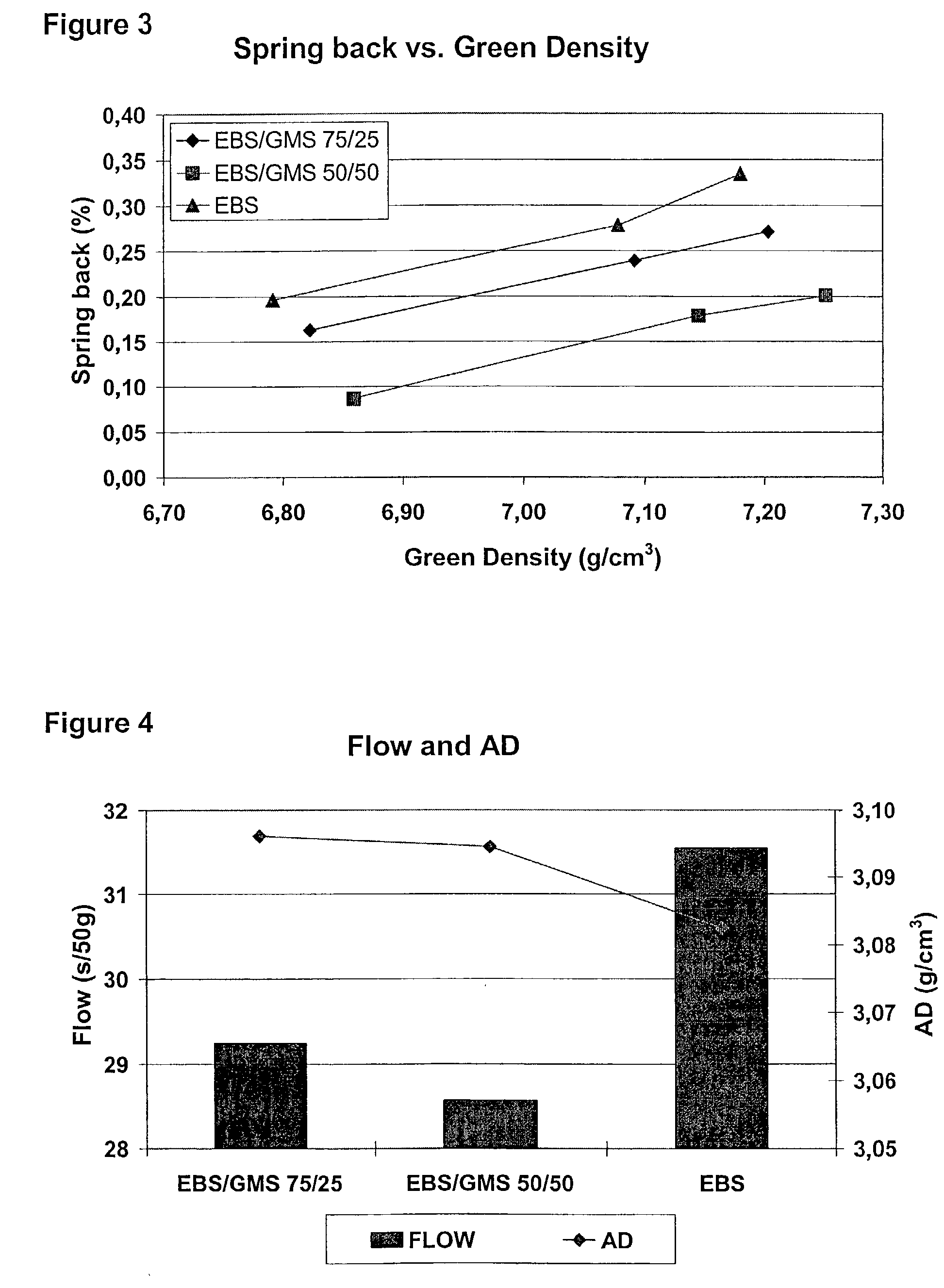
[0014] A third object of the invention is to provide an iron-based powder metal composition having good flow and comprising a lubricant which is free of zinc.
[0016] As used in the description and the appended claims, the expression "iron-based powder" encompasses powders prepared by atomisation, preferably water atomisation. Alternatively, the powder may be based on sponge iron. The powders may be made up essentially of pure iron; iron powder that has been pre-alloyed with other substances improving the strength, the hardening properties, the electromagnetic properties or other desirable properties of the end products; and particles of iron mixed with particles of such alloying elements (diffusion annealed mixture or purely mechanical mixture). Examples of alloying elements are copper, molybdenum, chromium, nickel, manganese, phosphorus, carbon in the form of graphite, and tungsten, which are used either separately or in combination, e.g. in the form of compounds (Fe.sub.3P and FeMo). Unexpectedly good results are obtained when the lubricants according to the invention are used in combination with iron-based powders having high compressibility. Generally, such powders have a low carbon content, preferably below 0.04% by weight. Such powders include e.g. Distaoly AE, Astaloy Mo and ASC 100.29, all of which are commercially available from Hogans AB, Sweden. The particles of iron based powders will have a weight average particle size in the range of above about 10 microns. Preferred are iron or pre-alloyed iron particles having a maximum weight average particle size up to about 350 microns; more preferably the particles will have a weight average particle size in the range of about 25-150 microns, and most preferably 40-100 microns.

Problems solved by technology

The use of external, die wall lubricants can reduce or eliminate the need for an internal lubricant, but problems accompany external lubrication techniques.
First, the film thickness within the die cavity has a tendency to vary, and the lubricant dispersion is known to drip out of the die cavity during processing.
Also, aqueous dispersions are a source of rust formation on the die cavity.
Another problem is that various external lubricant compositions are not necessarily sufficient to adequately lower ejection forces, especially at higher compaction pressures.
Finally, as a technique, the die wall lubrication does not permit high productivity in comparison with internal lubrication.
One problem is that the lubricant generally has a density of about 1-1.2 g / cm.sup.3 , as compared with the density of the iron-based powder, which is about 7-8 g / cm.sup.3.
Second, internal lubricants are generally not sufficiently effective for reducing the ejection pressures when manufacturing parts having part heights in excess of about 2.5-5 cm.
Another problem is, when the particles of internal lubricant burn off during sintering, pore spaces can be left in the compacted part, providing a source of weakness for the part.
Many presently used lubricants also have the disadvantage of requiring high energies for ejecting the green compact from the die.
Another disadvantage with presently used lubricants is that they often include zinc stearate.
Unfortunately, on contacting the cooler parts of the furnace or the outside atmosphere, the zinc tends to condense or reoxidise.
The most serious disadvantage is its poor flow behaviour in metal powders.

Method used


Image

  • Powder composition
  • Powder composition
  • Powder composition

Examples


Embodiment Construction

[0027] The following example, which is not intended to be limiting, present certain embodiments and advantages of the present invention. Unless otherwise indicated any percentages are on a weight basis.

[0028] The mixtures listed in table 1 below were prepared:

1TABLE 1 Sample GMS* EBS** 1 0 100 2 25 75 3 50 50 *Glyceryl monostearate **Etylene bisstearamide

[0029] The iron-based powder in all samples was ASC100.29 which is a water atomised, high purity iron powder available from Hogans AB, Sweden. The total amount of lubricant was 0.8% which was admixed in the powder composition together with 0.5% graphite(C-uf4) . The dry ingredients in the different test mixtures i.e. the iron powder, the lubricant and the graphite were blended to homogenous mixtures and added to a die cavity before compaction. The compaction operation was performed with the different powder mixtures at 400, 600 and 800 MPa at ambient temperature.

[0030] The different test mixtures were tested as regards green density...


PUM

PropertyMeasurementUnit
densityaaaaaaaaaa
densityaaaaaaaaaa
melting pointaaaaaaaaaa

Abstract

The present invention concerns a metal powder composition for the powder metal industry, wherein the metal powder is selected from the group consisting of an atomised iron-based powder or a sponge iron powder, and a lubricant composition comprising glyceryl stearate.

Description

[0001] The present invention relates to a metal powder composition for the powder metal industry. Particularly the invention relates to an iron-based metal powder composition comprising glyceryl stearate as lubricant.[0002] In industry the use of metal products manufactured by compacting and sintering iron-based powder compositions is becoming increasingly widespread. A number of different products of varying shapes and thickness are being produced. One processing technique for manufacture the products from the base powders is to charge the powder into a die cavity and compact the powder under high pressures. The obtained compact is then removed from the die cavity and sintered.[0003] The quality requirements of the products are continuously raised, and in this context one important factor is that the manufactured products have high and consistent density. Much effort is put into research to develop such products and one field within this research concerns lubrication, which is used...

Claims


Application Information

Patent Timeline
Patent Type & Authority Applications(United States)
IPC IPC(8): B22F1/10B22F3/02C10M169/04
CPCB22F1/0059B22F2998/00C10N2210/02C10N2210/01C10M2215/0806C10M169/04C10M2207/1253C10M2207/126C10M2207/283C10M2207/2835C10M2207/289C10M2207/2895C10M2215/08B22F9/082B22F1/0003C10N2010/02C10N2010/04B22F1/10B22F1/09B22F1/12
Inventor RAMSTEDT, MARIAKNUTSSON, PER
Owner HOGANAS AB
Learn More