Multi-functional energy conditioner

a multi-functional, energy conditioner technology, applied in the direction of feed-through capacitors, emergency protective arrangements for limiting excess voltage/current, fixed capacitor details, etc., can solve the problems of requiring extensive repair and/or replacement at a great cost, affecting the operation of electronic equipment, and prone to stray electrical energy, so as to prevent debilitating electromagnetic emissions, minimize or suppress unwanted electromagnetic emissions, and maintain constant apparent voltage potential

Inactive Publication Date: 2004-01-15
X2Y ATTENUATORS L L C
View PDF99 Cites 55 Cited by
  • Summary
  • Abstract
  • Description
  • Claims
  • Application Information

AI Technical Summary

Benefits of technology

0012] Based upon the foregoing, there has been found a need to provide a multi-functioning electronic component which can operate across a broad frequency range as compared to a single, prior art component or a multiple passive network. Ideally, this component would perform effectively past 1 GhZ while simultaneously providing energy decoupling for active componentry and maintaining a constant apparent voltage potential for portions of active circuitry. This new component would also minimize or suppress unwanted electromagnetic emissions resulting from differential and common mode currents flowing within electronic circuits. A multi-functioning electronic component in a multi-layered embodiment and in a dielectric independent passive architecture can, when attached into circuitry and energized, be able to provide simultaneous line conditioning functions such as, but not limited to, the forgoing needs. These needs include source to load and/or load to source decoupling, as well as, differential and common mode filtering, parasitic containment, and surge protection

Problems solved by technology

These components can be very susceptible to stray electrical energy created by electromagnetic interference or voltage transients occurring on electrical circuitry servicing or utilizing these systems.
Voltage transients can severely damage or destroy such micro-electronic components or contacts thereby rendering the electronic equipment inoperative, often requiring extensive repair and/or replacement at a great cost.
Other sources of interference are also generated from equipment as it operates, coupling energy to the electrical circuitry, which may generate significant interference.
In a similar manner, electromagnetic pulses (EMP) can generate large voltage spikes with fast rise time pulses over a broad frequency range that are detrimental to most electronic devices.
Other sources of large voltage transients as well as ground loop interference caused by varying ground potentials can disrupt an electrical system.
Existing protection devices are unable to provide adequate protection in a single integrated package.
Electrical systems have undergone short product life cycles over the last decade.
However, with the advent of new generations of microprocessors, memory components and their data, there is intense pressure to provide the user increased processing power and speed at a decreasing unit cost.
As a result, the engineering challenge of conditioning the energy delivered to electrical devices has become both financially and technologically difficult.
During this same period, passive componentry technologies have failed to keep up and have produced only incremental changes in composition and per

Method used


Image

  • Multi-functional energy conditioner
  • Multi-functional energy conditioner
  • Multi-functional energy conditioner

Examples


Embodiment Construction

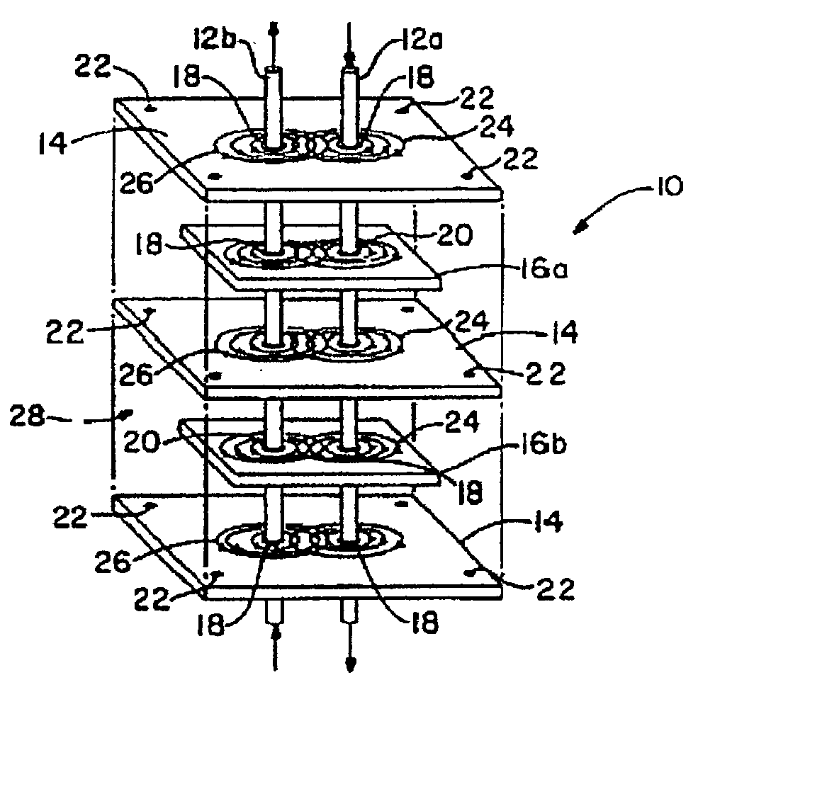
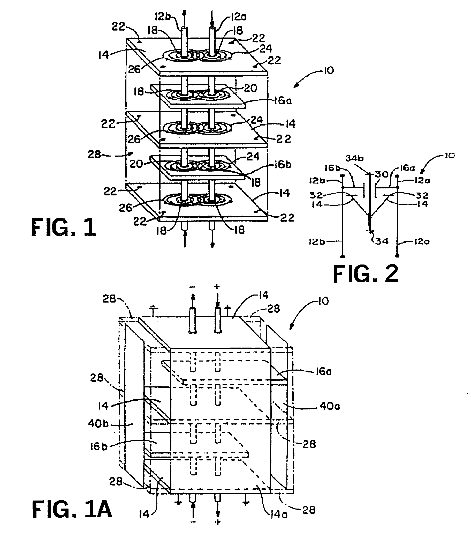
[0047] Continued and increasing use of electronics in daily life and the amount of electromagnetic interference (EMI) and emissions generated has created new electromagnetic compatibility (EMC) requirements. These new specifications apply to diverse electronic equipment such as but not limited to and in particular IC (Integrated Circuit) packages, PCBs, DSPs, microcontrollers, switch mode power supplies, networks, connectors, avionics, wireless phones, consumer electronics, tools, ordnance igniters, and control equipment. The present invention is directed towards a physical architecture for an electronic component that provides simultaneous and effective EMI suppression; line conditioning, broadband I / O-line filtering, EMI decoupling noise reduction and surge protection in one integrated component or assembly.

[0048] To propagate electromagnetic interference energy two fields are required, an electric and magnetic. Electric fields couple energy into circuits through the voltage diffe...


PUM


Abstract

The present invention relates to a multi-functional energy conditioner having architecture employed in conjunction with various dielectric and combinations of dielectric materials to provide one or more differential and common mode filters for the suppression of electromagnetic emissions and surge protection. The architecture allows single or multiple components to be assembled within a single package such as an integrated circuit or connector. The component's architecture is dielectric independent and provides for integration of various electrical characteristics within a single component to perform the functions of filtering, decoupling, fusing and surge suppression.

Description

TECHNICAL FIELD[0001] This application is a continuation of application Ser. No. 09 / 946,190, filed Sep. 5, 2001, which is a continuation of application Ser. No. 09 / 579,606 filed May 26, 2000, which is a continuation-in-part of application Ser. No. 09 / 460,218 filed Dec. 13, 1999, which is a continuation of application Ser. No. 09 / 056,379 filed Apr. 7, 1998, now issued as U.S. Pat. No. 6,018,448, which is a continuation-in-part of application Ser. No. 09 / 008,769 filed Jan. 19, 1998, now issued as U.S. Pat. No. 6,097,581, which is a continuation-in-part of application Ser. No. 08 / 841,940 filed Apr. 8, 1997, now issued as U.S. Pat. No. 5,909,350. The disclosures of all of the foregoing applications are incorporated herein by reference.[0002] The present invention relates to a multi-functional energy conditioner that possesses a commonly shared centrally located conductive electrode of the structure that can simultaneously interact with energized and paired differential electrodes as sai...

Claims


Application Information

Patent Timeline
IPC IPC(8): H01L23/50H01L23/552H03H1/00H05K1/14H05K1/16H05K3/34H05K9/00
CPCH01G4/012H01G4/30H01L2924/0002H01G4/35H01L23/50H01L23/552H01L2924/3011H01L2924/3025H03H1/0007H03H2001/0014H05K1/141H05K1/162H05K3/3436H05K9/0039H01L2924/00
Inventor ANTHONY, ANTHONY A.ANTHONY, WILLIAM M.
Owner X2Y ATTENUATORS L L C
Why Eureka
Try Eureka