Engraving sheet and method of engraving the same

Active Publication Date: 2004-02-05
SUZUKI CO LTD Y
View PDF12 Cites 4 Cited by
  • Summary
  • Abstract
  • Description
  • Claims
  • Application Information

AI Technical Summary

Problems solved by technology

However, the determination method dependent on the reflected light only needs a complicated technique.
Since the engraving sheet is not solvent resistant to petroleum-based, aromatic, ketonic, and ester solvents in particular, the sheet is hard to counterfeit.
Because of its nonadhesive quality with other materials, restoring the engraving sheet using another material is difficult once the

Method used


Image

  • Engraving sheet and method of engraving the same
  • Engraving sheet and method of engraving the same

Examples


example 2

[0025] An undercoat paint (Acronal YJ2721D, Tradename of Mitsubishi Yuka Badische Co., Ltd.) was applied on an electron-beam cross-linked, biaxially oriented high-density polypropylene support layer having a thickness of 60 .mu.m, to a thickness of 1 g / m.sup.2 at dry weight, and a paint containing the following compositions was then applied on the undercoat paint, thereby forming an engraving layer.

1 Acrylic based emulsion 50 weight % (Acronal S-886S, Tradename of Mitsubishi Yuka Badische Co., Ltd.) Calcium carbonate 90 weight % Titanium white 10 weight % Dispersant 0.3 weight % Anti-foaming agent 0.1 weight % Mildew-proofing agent 0.2 weight % Ultraviolet absorber 0.3 weight %

[0026] The thickness of the engraving layer subsequent to a drying operation was 17 .mu.m. A basic pattern was printed in the area other than an engraved region and a signature region. The positive image and the negative image under the presence of the reflected light were obtained, resulting in an engraved im...

example 3

[0027] The thickness of the biaxially oriented high-density polypropylene sheet was varied to vary opacity of an engraving sheet having the same engraving layer as that of Example 2, as listed in Table 1. A card printing machine as an engraving device was used to engrave the same image, and resulting engraved sheets were compared to each other.

2 TABLE 1 SUPPORT LAYER ENGRAVING LAYER OPACITY TEST THICKNESS OPACITY THICKNESS OPACITY SHARP- DIFFER-No. .mu.m % .mu.m % NESS ENCE % 1 40 15 17 55 .largecircle. 40 2 45 18 17 55 .largecircle. 37 3 55 20 17 55 .largecircle. 35 4 60 25 17 55 .DELTA. 30 5 65 27 17 55 .DELTA. 28 6 70 30 17 55 .DELTA. 25 7 75 33 17 55 .DELTA. 22 8 80 35 17 55 .DELTA. 20 9 85 38 17 55 X 17 10 90 42 17 55 X 13 11 100 50 17 55 X 5 Notes .largecircle.: HIGH .DELTA.: MIDDLE X: LOW

[0028] As seen from Table 1, at the middle sharpness at which the opacity difference ranges from 20% to 30%, the reflected light image is slightly less sharp, but the resulting engraved image...

example 4

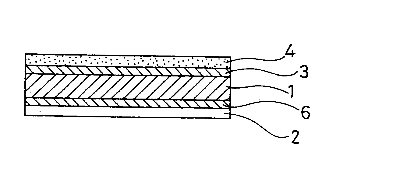
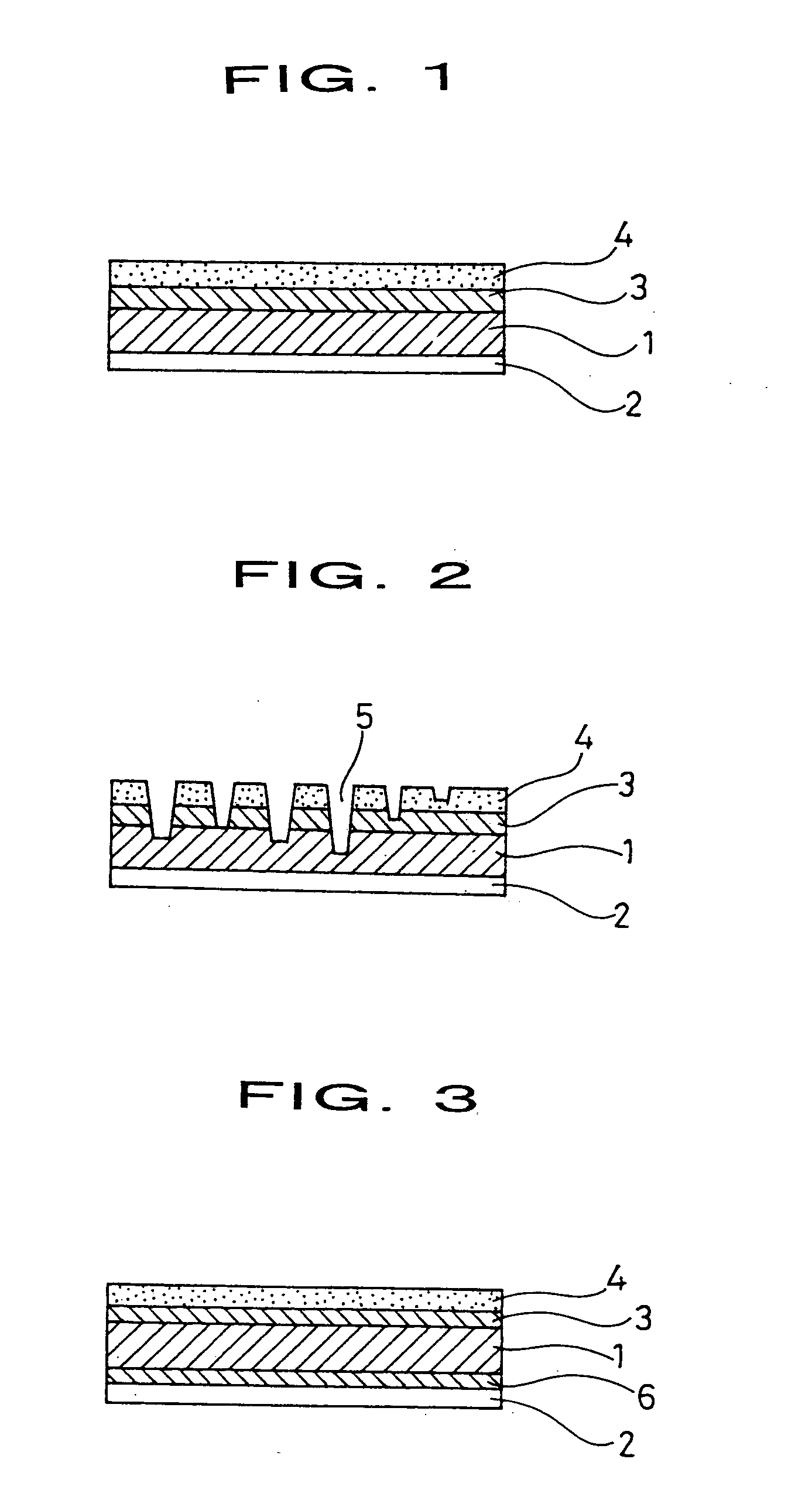
[0029] Referring to FIG. 1, a liner layer 2 was attached on the back side of the support layer 1 fabricated of the biaxially oriented high-density polypropylene sheet as thick as 60 .mu.m. An undercoat layer 3 is arranged on the support layer 1 by applying a white offset ink, and an engraving layer 4 was then deposited on the undercoat layer 3. The engraving sheet thus resulted. Referring to FIG. 2, by engraving the engraving sheet so deeply that a reversed picture signal becomes close to a black level, the engraved image becomes a positive image under the presence of the reflected light. The engraved image becomes a negative image under the presence of the transmitted light entering from behind. Referring to FIG. 3, a basic pattern printing layer 6 may be deposited beneath the support layer 1 using a white offset ink.


PUM

PropertyMeasurementUnit
Fractionaaaaaaaaaa
Fractionaaaaaaaaaa
Fractionaaaaaaaaaa

Abstract

An engraving sheet includes a support layer fabricated of biaxially oriented high-density polypropylene, and an engraving layer formed on the support layer and having an opacity of 40%. The engraving sheet is engraved from the engraving layer down to the support layer. The support layer is lower in opacity than the engraving layer with a difference of 20% or more between the opacity of the support layer and the opacity of the engraving layer. The engraving sheet allows a desired pattern, a photograph of the face of an individual, or the like to be engraved thereon, and presents a finger touch similar to that of paper, and is hard to be torn even after it is bound by a sewing machine or a stapler.

Description

BACKGROUNDOF THE INVENTION[0001] 1. Field of the Invention[0002] The present invention relates to an engraving sheet having a support layer and an engraving layer formed on the support layer with the engraving layer to be engraved in accordance with a desired pattern, a photograph of the face of an individual or the like down to a depth to the support layer, and a method of engraving the engraving sheet.[0003] 2. Description of the Related Art[0004] In known anti-counterfeit techniques, an image is engraved on an identification card, a passport, a bank book, or a plastic sheet of a variety of cards for identification, and a reflected light bearing the image is checked to see if it is a genuine engraved image. However, the determination method dependent on the reflected light only needs a complicated technique. Japanese Unexamined Patent Application Publication No. 6-15794 discloses an engraving sheet that is formed of a support layer and an engraving layer formed on the support laye...

Claims


Application Information

Patent Timeline
IPC IPC(8): B32B27/32B42D15/00B42D15/10B44C3/02
CPCB42D2035/30B42D25/00Y10T428/24331Y10T428/24355Y10T428/24802B42D25/309Y10T428/31909B42D25/44
Inventor SUZUKI, AKIRA
Owner SUZUKI CO LTD Y
Why Eureka
Try Eureka