
Color conversion filter, color conversion layer and color conversion light emitting device

a color conversion filter and color conversion technology, applied in the field of color conversion filters, can solve the problems of difficult to obtain an organic light-emitting device emitting bright white light for a long time, difficult to increase the content of fluorescence conversion dyes, and difficult to produce such devices at a low cos

Inactive Publication Date: 2004-03-18
FUJI ELECTRIC CO LTD
View PDF2 Cites 34 Cited by
  • Summary
  • Abstract
  • Description
  • Claims
  • Application Information

AI Technical Summary

Benefits of technology

[0014] It is another object of the present invention to provide a color conversion layer having a structure in which high color conversion efficiency of the fluorescence conversion dye is maintained, and decomposition of the dye is suppressed.
[0015] It is a further object of the invention to provide a fluorescence conversion dye for a color conversion filter with high efficiency even at a low content.

Problems solved by technology

In the method of displaying multiple or full colors with the organic EL display, it is necessary to arrange the three types of light-emitting materials (R, G, and B) in a matrix form with high precision, thereby making it technically difficult to produce such a device at a low cost.
However, it is difficult to obtain an organic light emitting device emitting bright white light for a long time, which is necessary for obtaining bright three colors R, G, and B.
A major problem in improving the color conversion efficiency of a color conversion filter is that it is difficult to increase a content of fluorescence conversion dye.
Therefore, when the fluorescence conversion dye is contained at a high concentration, even though the efficiency thereof is optimized at an initial stage, the color conversion efficiency is abruptly reduced while the dye is in service.

Method used


Image

  • Color conversion filter, color conversion layer and color conversion light emitting device
  • Color conversion filter, color conversion layer and color conversion light emitting device
  • Color conversion filter, color conversion layer and color conversion light emitting device

Examples


example 2

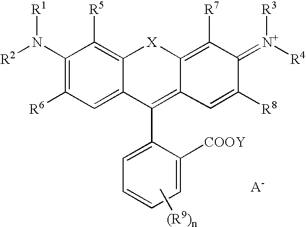
[0064] 92 mg of the dendrimer section having the chemical structure (2) (10 micromoles) and 5.0 mg (10 micromoles) of rhodamine B were used instead of 97 mg of the rhodamine B-dendrimer bonded body used in the Example 1. The same process was repeated to obtain a color conversion filter.

EXAMPLE 3

[0065] 19 mg of the rhodamine B-dendrimer bonded body having the chemical structure (1) (containing 1.0 mg (2 micromoles) of rhodamine B) was used. The same process was repeated to obtain a color conversion filter.

example 3

[0072] Example 3 and Comparative Example 2 provide a comparison of the color conversion filters containing a relatively low concentration of rhodamine B. Example 3 containing fluorescence-conversion-dye-dendrimer bonded body exhibits conversion efficiency at the initial stage approximately equivalent to that of Comparative Example 2 containing no dendrimer. Example 3 exhibits durability superior to that of Comparative Example 2. It is considered that the result is associated with the suppression of the interaction among the fluorescence conversion dyes by the dendrimer.

[0073] As described above, the fluorescence conversion dye is chemically bonded to the dendrimer or the fluorescence conversion dye included in the dendrimer is in the clathrate state. Therefore, it is possible to obtain the color conversion layer containing the fluorescence conversion dye at a high concentration without the reduction in the conversion efficiency due to the concentration quenching and the decompositio...


PUM


Abstract

A color conversion layer includes a matrix resin, a fluorescence conversion dye and a dendrimer for converting a wavelength distribution of incident light and emitting a converted light. The fluorescence conversion dye and the dendrimer may be chemically bonded to each other via a covalent bond. Alternatively, the dendrimer may include the fluorescence conversion dye in a clathrate state.

Description

BACKGROUND OF THE INVENTION AND RELATED ART STATEMENT[0001] The present invention relates to a color conversion filter with good environmental resistance and high productivity for displaying multiple colors with high definition. In particular, the invention relates to a color conversion filter used for a display in an image sensor, personal computer, word processor, television, facsimile device, audio system, video system, car navigation system, electronic calculator, telephone, personal digital assistant and industrial measuring instrument.[0002] In recent years, the information technology has been rapidly advanced. A display device used in the information technology has been required to have a better aesthetic appearance, a lighter weight, a thinner thickness and higher performance. Furthermore, a great effort has been made to reduce power consumption and increase a response speed. In particular, many attempts have been made to develop a high-definition full-color display device.[...

Claims


Application Information

Patent Timeline
IPC IPC(8): C09K11/06H05B33/12G02B5/20H01L51/50
CPCC09K11/06C09K2211/1007C09K2211/1011G02B5/201C09K2211/1022C09K2211/1088C09K2211/1014
Inventor KAWAGUCHI, KOJIKOBAYASHISAKURAI, KENYA
Owner FUJI ELECTRIC CO LTD
Learn More