
Sliding component

Inactive Publication Date: 2004-03-18
ARAKAWA CHEM IND LTD
View PDF12 Cites 24 Cited by
  • Summary
  • Abstract
  • Description
  • Claims
  • Application Information

AI Technical Summary

Benefits of technology

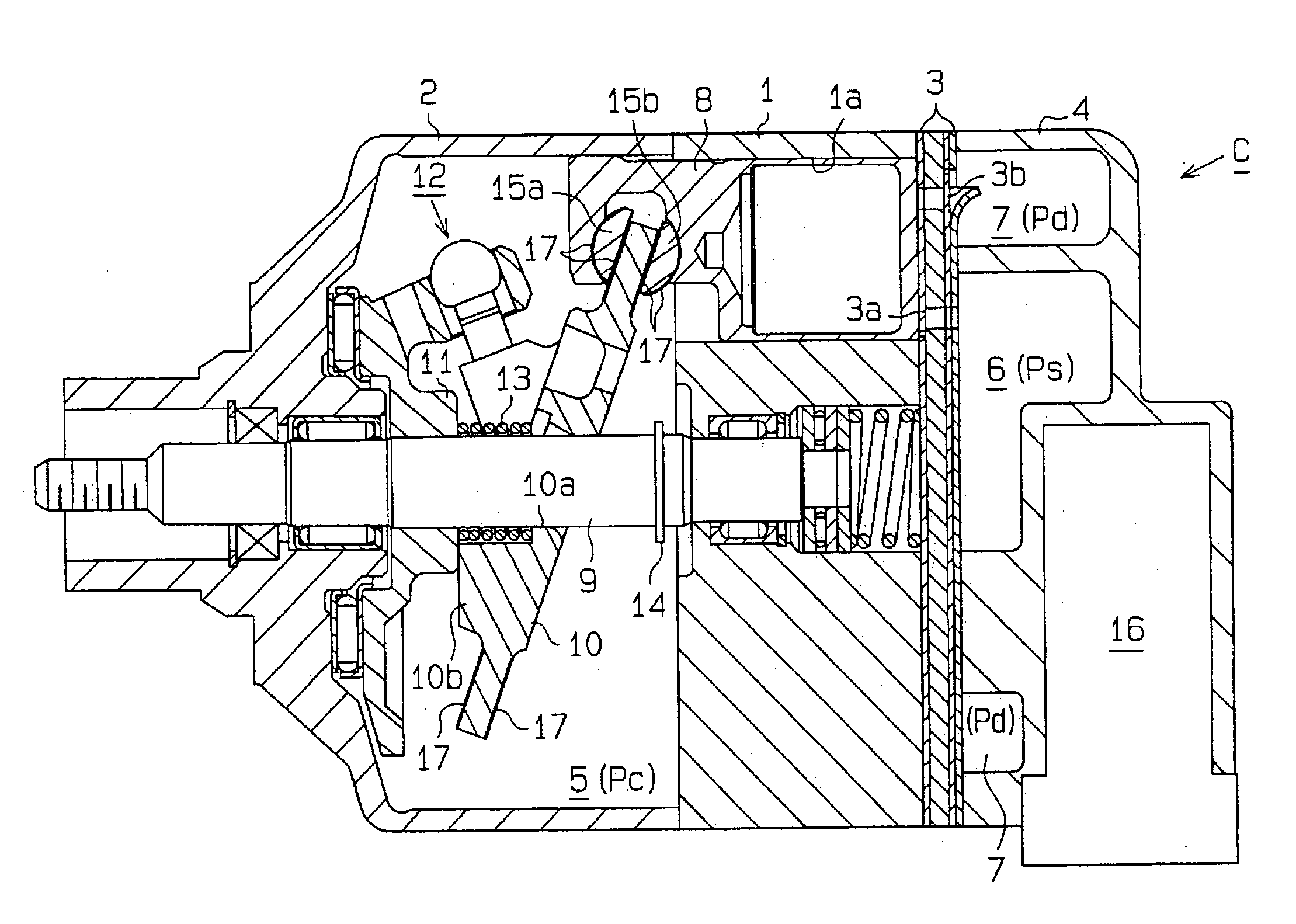
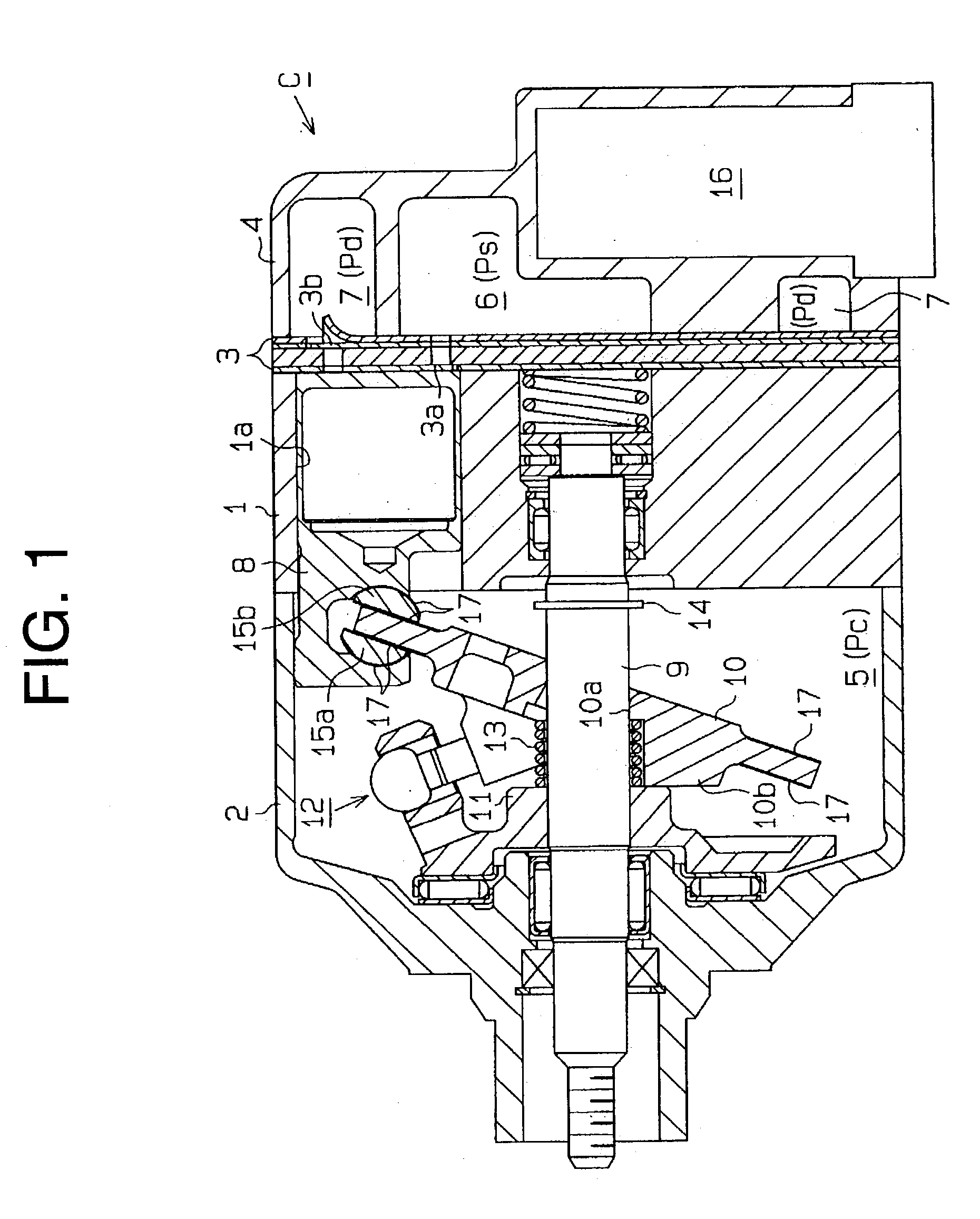
[0037] The opening degree of the control valve 16 is adjusted in response to cooling load of the compressor C, thus varying the amount of refrigerant communicated from the discharge chamber 7 to the crank chamber 5. When the cooling load is high and pressure in the suction chamber 6 (suction chamber pressure Ps) is high, the opening degree of the control valve 16 reduces. As a result, the crank chamber pressure Pc reduces, and the inclination angle of the swash plate 10 increases. Then the stroke of the pistons 8 increases so that the compressor C is operated in a relatively large displacement volume. On the other hand, when the cooling load is low and the suction chamber pressure Ps is low, the opening degree of the control valve 16 increases. As a result, the crank chamber pressure Pc increases, and the inclination angle of the swash plate 10 reduces. Then, the stroke of the pistons 8 reduces so that the compressor C is operated in a relatively small displacement volume.
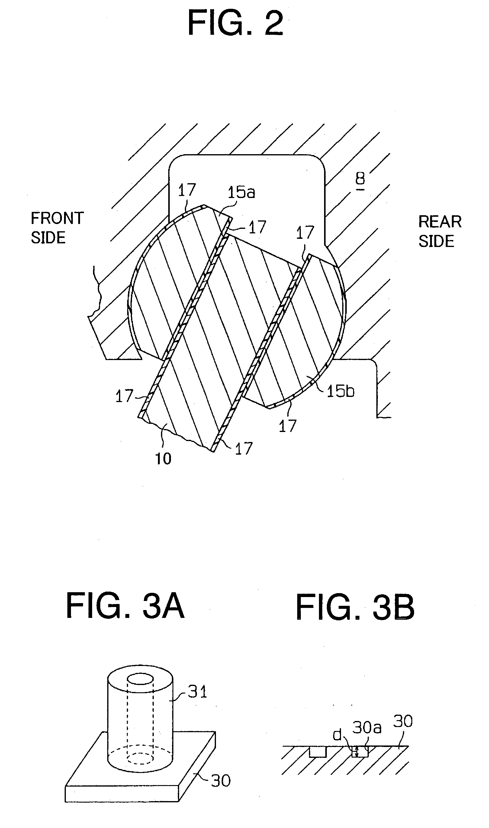
[0038] Since the silane-modified resin layers 17 are formed on the sliding surfaces of the swash plate 10 and the shoes 15a, 15b, sliding performance and durability improve at the sliding surfaces. Accordingly, reliability and durability of the compressor C improve.

Problems solved by technology

However, when the compressor is restarted after it has been left stopped for a long time, lubricating oil on the sliding portions is possibly washed away by refrigerant gas.
During this period, the sliding portions that need lubrication are insufficiently lubricated while the compressor is operating.
The conventional coating layers of tin or copper are insufficient to achieve sliding performance in such a severe condition.

Method used


Image

  • Sliding component
  • Sliding component
  • Sliding component

Examples


example 1

[0042] Silane-modified polyamideimide resin varnish (30 weight percent of the solid component of PAI resin and NMP / xylene solvent) containing 2 weight percent of silica in its cured residue is prepared. The above resin varnish is applied by a barcoater on an aluminum base member, the surface of which has been degreased. The aluminum base member with the resin varnish is calcined for 30 minutes at 80.degree. C., for 30 minutes at 150.degree. C. and then for 30 minutes at 200.degree. C. Thus, a layer having a thickness of 20 .mu.m is formed on the aluminum base member.

example 2

[0044] Solid lubricant is added to silane-modified polyamideimide resin varnish (30 weight percent of the solid component of PAI resin and NMP / xylene solvent) containing 2 weight percent of silica in its cured residue. After the mixture of the resin varnish and the solid lubricant has been agitated, it is passed through a roll mill twice. Thus, a material for coating is prepared. PTFE powder, MoS.sub.2 powder and graphite powder are added together as the solid lubricant. The coating material is applied on the degreased surface of an aluminum base member by a barcoater and is calcined for 30 minutes at 80.degree. C., for 30 minutes at 150.degree. C. and then for 30 minutes at 200.degree. C. Thus, a layer having a thickness of 20 .mu.m is formed on the aluminum base member. The composition rate of the solid component of the coating material is 65 weight percent of silane-modified polyamideimide resin, 10 weight percent of PTFE, 20 weight percent of MoS.sub.2 and 5 weight percent of gr...

example 3

[0046] Curing agent (phenol novolac resin), silane curing catalyst (tin 2-ethyl hexanoic acid) and solid lubricant are added to silane-modified epoxy resin varnish (50 weight percent of epoxy resin and MEK solvent) containing 36 weight percent of silica in its cured residue. After the mixture of the resin varnish, the curing agent, the catalyst and the solid lubricant has been agitated, a material for coating is prepared. PTFE powder, MoS.sub.2 powder and graphite powder are added together as the solid lubricant. The coating material is applied on the degreased surface of an aluminum base member by a barcoater and is calcined for 30 minutes at 100.degree. C. and then for 60 minutes at 200.degree. C. Thus, a layer having a thickness of 20 .mu.m is formed on the aluminum base member. The composition rate of the solid component of the coating material is 65 weight percent of silane-modified polyamideimide resin, 10 weight percent of PTFE, 20 weight percent of MoS.sub.2 and 5 weight per...


PUM


Abstract

A sliding component has a metal base member and a coating layer. The metal base member has a sliding surface. The layer is made of silane-modified resin. The silane-modified resin is made from resin that is soluble in solvent and is equal to or higher in heat-resistant than epoxy resin. The coating layer is formed on the sliding surface.

Description

[0001] The present invention relates to sliding components such as a swash plate and a piston in a compressor for a vehicle air-conditioning system.[0002] A compressor includes some sliding components in its inner mechanism. Generally, gas (for example, refrigerant gas such as chlorofluorocarbon) circulates in the compressor in accordance with the operation of the compressor. The gas atomizes lubricating oil stored in the compressor and transfers the atomized lubricating oil to the sliding portions of the respective sliding components so as to lubricate the sliding portions between the sliding components. However, when the compressor is restarted after it has been left stopped for a long time, lubricating oil on the sliding portions is possibly washed away by refrigerant gas.[0003] For example, in a swash plate type compressor, pistons are coupled with a swash plate through shoes and reciprocate in respective cylinder bores by the rotation of the swash plate or by the oscillation of...

Claims


Application Information

Patent Timeline
IPC IPC(8): F04B27/08F04B27/10
CPCF04B27/0878F04B27/1054F04B27/0886F04B27/08
Inventor MURASE, HITOTOSHISHIMO, TOSHIHISA
Owner ARAKAWA CHEM IND LTD
Learn More