
Resin composition, process for producing the same and electrophotographic fixing member

Inactive Publication Date: 2004-03-25
FUJIFILM BUSINESS INNOVATION CORP
View PDF13 Cites 7 Cited by
  • Summary
  • Abstract
  • Description
  • Claims
  • Application Information

AI Technical Summary

Problems solved by technology

However, in the method in which the adhesion is conducted with the adhesive as noted above, an adhesion strength is less reliable when the metallic thin film is repeatedly subjected to electromagnetic induction heating.
Also in the method in which the metallic thin film is formed on the heat-resistant resin, it is generally difficult to firmly adhere a heat-resistant resin such as a polyimide or an aromatic polyamide (aramid) to a metallic thin film of copper.
However, according to a method in which a heat-resistant resin is molded and a metallic thin film is then formed thereon as in the ordinary techniques, no satisfactory adhesion is obtained or a production process is hardly rationalized.
However, the film member of the liquid crystal polymer is generally oriented drastically in the molding and tends to be torn unidirectionally.

Method used


Image

  • Resin composition, process for producing the same and electrophotographic fixing member
  • Resin composition, process for producing the same and electrophotographic fixing member

Examples


example 1

[0077] An N,N-dimethylacetamide solution of a polyamic acid as a polyimide precursor (trade name: U Varnish, made by Ube Industries, Ltd., polyimide precursor solution) is used. A solid content is adjusted to 20%, and a viscosity to approximately 1 Pa.multidot.s respectively.

[0078] A glass plate having a thickness of 0.2 mm and a size of 20.times.150 mm is used as a substrate, and dipped in the polyimide precursor solution by making the longitudinal direction vertical. Then, the plate is withdrawn at a rate of 100 mm / min to form a polyimide precursor film.

[0079] Subsequently, a solvent substitution rate control member (U Pore UP2015, gas permeability 550 sec / 100 cc: made by Ube industries, Ltd.) having many through-holes is coated on the surface of the polyimide precursor film, dipped in water, and allowed to stand for 1 minute. When the substrate is withdrawn, the surface of the polyimide precursor film has a porous structure with many pores.

[0080] Waterdrops are wiped out from the...

example 2

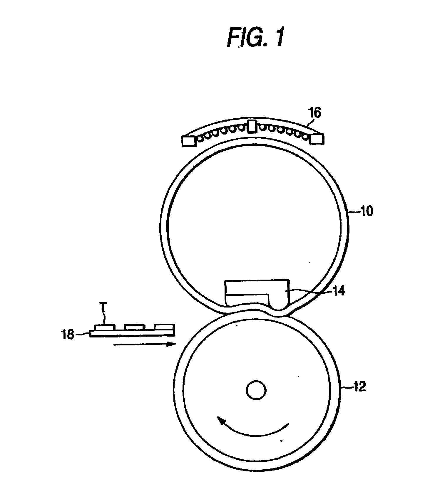
[0107] A fixing belt is produced as in Example 1 except that a polyimide resin layer having a porous structure on the surface and having a thickness of 20 .mu.m is formed by properly changing a viscosity of a polyimide precursor solution and a withdrawal rate of a substrate. When this fixing belt is evaluated as in Example 1, delamination does not occur in an interface between the polyimide resin layer and the metallic layer (heat generation layer).

example 3

[0108] A fixing belt is produced as in Example 1 except that a polyimide resin layer having a porous structure on the surface and having a thickness of 50 .mu.m is formed by property changing a viscosity of a polyimide precursor solution and a withdrawal rate of a substrate, and an elastic layer [obtained by coating and drying a silane coupling agent "KBE 903" (made by Shin-etsu Chemical Industry Co., Ltd.) and then coating and drying a liquid silicone rubber "KE1334" (made by Shin-etsu Chemical Industry Co., Ltd.): hardness 40.degree. (JIS-A)] and a release layer (same as in Example 1) are further formed on a metallic layer in this order. When this fixing belt is evaluated as in Example 1, delamination does not occur in an interface between the polyimide resin layer and the metallic layer (heat generation layer).


PUM

PropertyMeasurementUnit
Structureaaaaaaaaaa
Sizeaaaaaaaaaa
Metallic bondaaaaaaaaaa

Abstract

A resin composition having a high adhesion between a resin layer and a metallic layer as well as an excellent durability, a process for producing the same, and an electrophotographic fixing member are provided. In the resin composition, a metallic layer is provided on a surface of a resin layer having a porous structure at least on the surface.

Description

[0001] The present invention relates to a resin composition, a process for producing the same, and an electrophotographic fixing member. More specifically, it relates to a resin composition which has a metallic layer on a surface of a heat-resistant resin layer and which can advantageously be used in a printed circuit substrate and an electrophotographic member such as a fixing member, a process for producing the same, and an electrophotographic fixing member.DESCRIPTION OF THE RELATED ART[0002] A laminate in which a thin film of a conductive metal such as copper or aluminum is laminated on a thin plate made of a heat-resistant resin or a thin plate in which a core member is impregnated with a heat-resistant resin has so far found wide acceptance as a printed circuit substrate. Further, in an image forming apparatus of an electrophotographic system or an electrostatic recording system using a dry toner as well, a film in which a heat-resistant resin is laminate with a metallic thin ...

Claims


Application Information

Patent Timeline
IPC IPC(8): C23C18/16C23C18/20C23C18/40C25D5/34C25D5/48C25D5/56H05K3/18H05K3/38
CPCH05K2203/0759Y10T428/1376C23C18/1648C23C18/1653C23C18/1865C23C18/1882C23C18/40C25D5/56H05K3/181H05K3/381H05K2201/0116H05K2201/0154H01L2924/0002H05K2203/0783H01L2924/00Y10T428/249954Y10T428/24999Y10T428/249979Y10T428/249992Y10T428/249991
Inventor TAMEMASA, HIROSHIOMATA, MAKOTOOHTA, SHIGEOOKAYASU, TAKAHIRO
Owner FUJIFILM BUSINESS INNOVATION CORP
Learn More