
Organic light-emitting panel, package process for organic light-emitting panel and coating apparatus thereof

a light-emitting panel and organic technology, applied in the field of panels, can solve the problems of easy penetration of moisture through the adhesive frame, inability to completely protect, and dark spots and degradation of devices

Inactive Publication Date: 2004-05-13
RITDIPLAY
View PDF3 Cites 12 Cited by
  • Summary
  • Abstract
  • Description
  • Claims
  • Application Information

AI Technical Summary

Benefits of technology

[0012] Another object of the present invention is to provide a package process for organic light-emitting panel for reducing the crosslinking time of desiccant, increasing surface area of the desiccant and improving moisture-absorption ability thereof.
[0013] The other object of the present invention is to provide a package process for organic light-emitting panel for efficiently protecting the organic light-emitting panel from erosion due to moisture and oxygen.
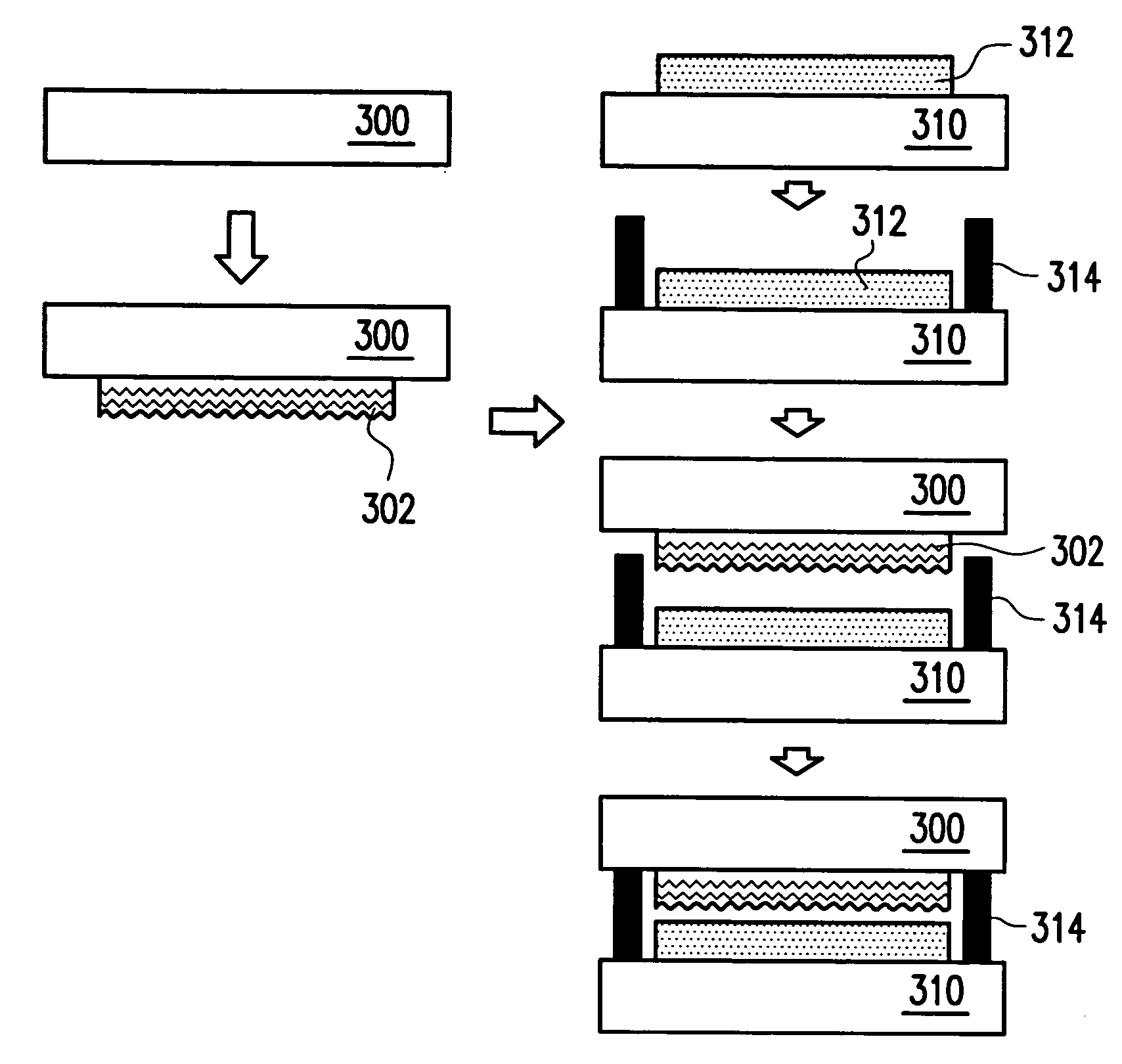
[0016] In addition, the present invention provides an organic light-emitting panel, which comprises a substrate having organic light-emitting devices; a cover plate over the substrate; a patterned desiccant on the cover plate, facing to the substrate having the organic light-emitting devices; and an adhesive frame between the substrate s and the cover plate. Because the patterned desiccant is formed on the cover plate, the crosslinking time of the patterned desiccant is reduced, the surface area of the desiccant is increased and the moisture absorption of the desiccant is enhanced. Moreover, the pattern of the patterned desiccant has a large surface area, such as continuous, discontinuous, solid or hollow patterns or the combination thereof.
[0018] The present invention uses the ink-jet printing process to increase the surface area of the desiccant on the cover plate. Therefore, the solvent within the desiccant can be easily evaporated during crosslinking process. Because of increase of the surface area of the desiccant, the moisture absorption efficiency of the desiccant is also improved.
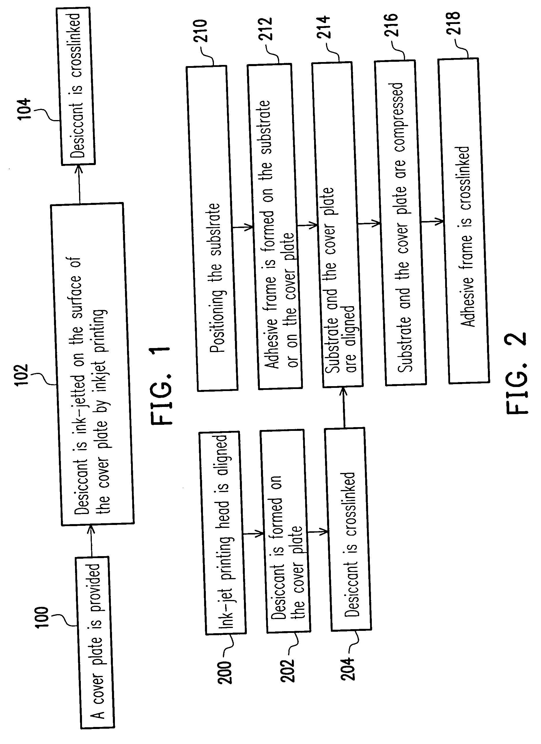
[0019] Additionally, the present invention uses an ink-jet printing heads or devices similar thereto for ink-jetting the desiccant on the cover plate and the desiccant is then crosslinked by a crosslinking process. The process time of the present invention is short and the desiccant is efficiently used. Therefore, the problems of the prior art packaging process are thus resolved, the process time is reduced, the manufacturing costs are also reduced and the organic light-emitting device is being protected.
[0020] Moreover, the package process for organic light-emitting panel of the present invention can protect the organic light-emitting devices from erosion due to moisture and oxygen.

Problems solved by technology

The organic functional material and the cathode in OLED easily interact with moisture and oxygen and leading to the formation of dark spots and degradation of devices.
However, because the adhesive frame is polymer and has a width about 1 mm, moisture easily penetrates through the adhesive frame.
Therefore, it cannot completely protect OLED from moisture and oxygen and the life time of OLED is shortened.
Therefore, non-illumination area or dark spots are generated and the device becomes degraded.
Although the coating process is a short time process, more than 90% desiccant is wasted and thereby increases the manufacturing costs.
In addition, the traditional process needs longer solidification time because the solvent of the desiccant is hard to evaporate.
It also has disadvantages of small moisture absorption area and poor moisture absorption ability.
Moreover, the process also needs longer solidification time because the solvent of the desiccant is hard to evaporate.

Method used


Image

  • Organic light-emitting panel, package process for organic light-emitting panel and coating apparatus thereof
  • Organic light-emitting panel, package process for organic light-emitting panel and coating apparatus thereof
  • Organic light-emitting panel, package process for organic light-emitting panel and coating apparatus thereof

Examples


third embodiment

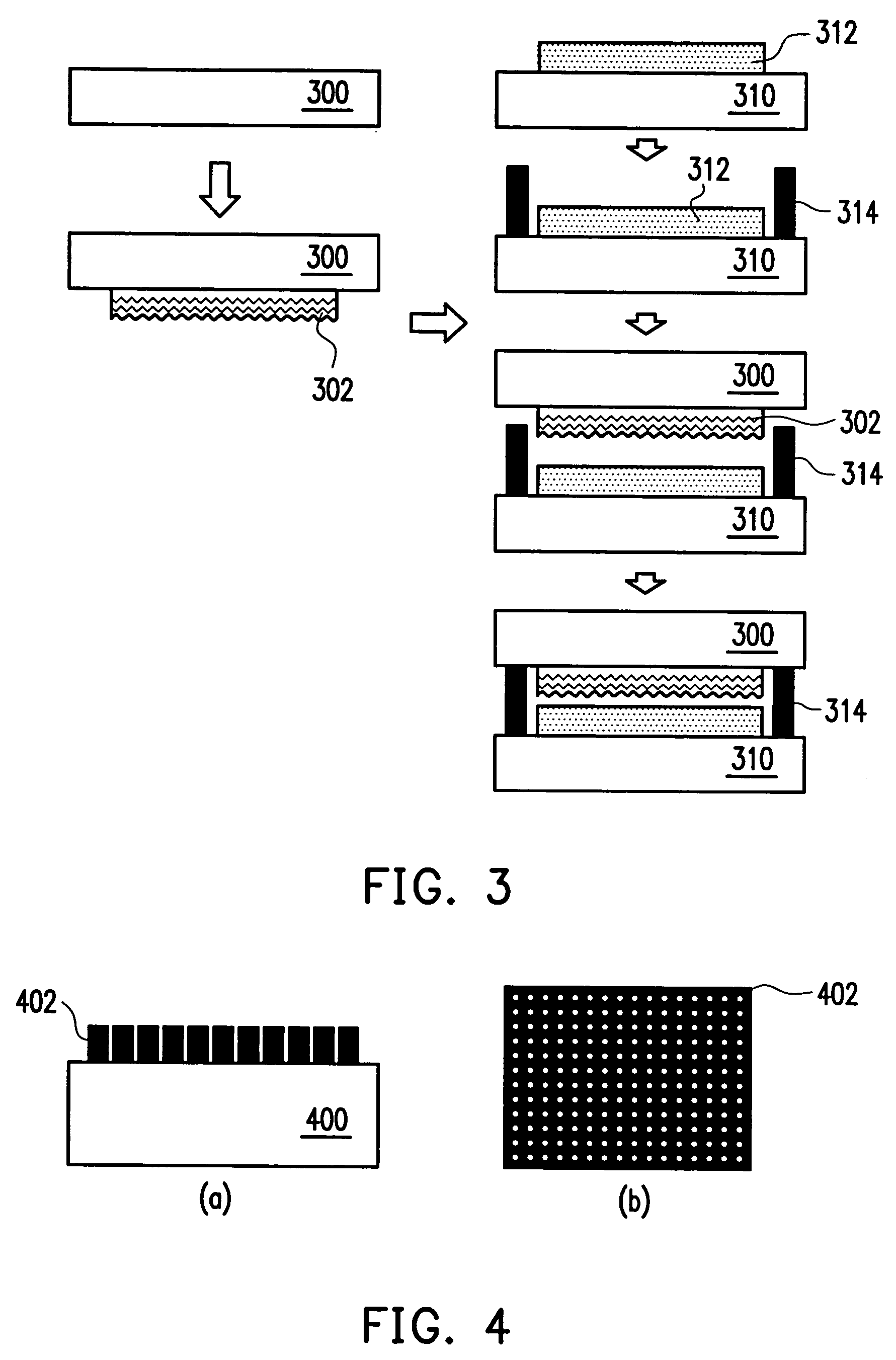
[0038] FIG. 4 is a top and cross-sectional views showing the cover plate and the desiccant of the present invention. Referring to FIG. 4(a), a patterned desiccant 402 is formed on the cover plate 400. The pattern of the desiccant 402 having a large surface area is formed by an ink-jet printing process, wherein the pattern of the desiccant can be a continuous shape as shown in FIG. 3, a discontinuous shape, such as triangle, rectangle, polygon, circle or a random shape in solid or hollow. Therefore, the solvent within the desiccant can be easily evaporated during the crosslinking process and the moisture absorption efficiency of the desiccant is improved.

fourth embodiment

[0039] The fourth preferred embodiment of the present invention is described below. The present invention also provides a coating apparatus as shown in FIG. 5. FIG. 5 is a schematic configuration showing a coating apparatus applied in the present invention. Referring to FIG. 5, the coating apparatus 500 comprises an ink-jet printing device 502, a crosslinking device 508 and a buffer chamber 510 for transferring the cover plate, wherein the ink-jet printing device 502 is, for example, at least one ink-jet printing head or devices similar thereto. The buffer chamber 510 is connected to the ink-jet printing device 502 and the crosslinking device 508. The arrangement of the ink-jet printing device 502, the buffer chamber 510 and the crosslinking device 508 are disposed in consideration of process flow. In addition, the coating apparatus further comprises a loading unit 504 and an unloading unit 506 for facilitating transfer of cover plates. The loading unit and unloading unit can be int...


PUM


Abstract

An organic light-emitting panel, a process for packaging an organic light-emitting panel and a coating apparatus applied thereto are described. A patterned desiccant with large surface area is formed on a cover plate by an ink-jet printing process. The process for packaging an organic light-emitting panel and the coating process are applied for reducing crosslinking time of the desiccant, increasing the surface area of the desiccant and enhancing the moisture absorption ability of the desiccant.

Description

[0001] This application claims the priority benefit of Taiwan application serial no. 91125118, filed Oct. 25, 2002.[0002] 1. Field of the Invention[0003] The present invention relates to a panel, a package process and a coating apparatus, and more particularly to an organic light-emitting panel, a package process for organic light-emitting panel and coating apparatus thereof.[0004] 2. Description of the Related Art[0005] Organic light-emitting devices (OLEDs) use illumination of organic functional material property for displaying. The device is formed by a pair of electrodes and an organic functional layer disposed between the electrodes and could be divided into small molecule OLED (SM-OLED) or polymer light-emitting device (PLED) depending on the organic functional material applied thereto.[0006] When current flows through the transparent anode and the metal cathode, holes and electrons will recombine within the organic functional layer and generate photons. The different colored ...

Claims


Application Information

Patent Timeline
Patent Type & Authority Applications(United States)
IPC IPC(8): H01L51/52H05B33/04
CPCH05B33/04H01L51/5237H10K59/8722H10K59/874H10K50/846H10K50/8426
Inventor WEI, MAO-KUOLAI, YUANG-WEI
Owner RITDIPLAY
Learn More