Method for reducing waste oxide gas emissions in industrial processes

a waste oxide gas and industrial process technology, applied in the field of new waste gas oxide gas emission reduction methods, can solve the problems of waste oxide gas producing undesirable effects, accelerating corrosion of buildings and monuments, and destroying waste, so as to reduce emissions, enhance destruction efficiency, and maximize residence time

Inactive Publication Date: 2004-05-20
DECOURCY MICHAEL STANLEY +2
View PDF11 Cites 23 Cited by
  • Summary
  • Abstract
  • Description
  • Claims
  • Application Information

AI Technical Summary

Benefits of technology

0059] In embodiments where significant liquid waste components are present in a given waste stream, such as when the waste stream comprises organic contaminated wastewater, it is preferred that at least a portion of the liquid waste components are injected into upstream zones of the thermal oxidizer. This upstream injection maximizes residence time and thereby enhances destruction efficiency. It is especially preferred that a portion of such liquid components are injected into the primary combustion zone.
0060] As previously described with respect to the horizontal thermal oxidizer 20, at least a portion of the reactive waste components injected into the vertical thermal oxidizer 120 are converted into reducing radicals within the waste destr

Problems solved by technology

If the waste stream is well mixed with the oxidant, and the waste is maintained at high temperature within the thermal oxidizer for a sufficient time period, waste destruction will occur through a combination of oxidation reactions.
When introduced to the environment, waste oxide gases can produce undesirable effects.
Sulfur-based oxides are associated with acidification of lakes and streams, accelerated corrosion of buildings and monuments, reduced visibility and adverse health effects.
Carbon-based oxides, most notably carbon monoxide, may present serious health concerns to the public and have been linked to global warming.
Such regulations are expected to become even more restrictive in the coming years.
Unfortunately these methods are of only limited utility.
All industrial boiler emission reduction methods involve substantial capital, operating, or maintenance costs.
Which makes these methods economically unattractive when applied to waste destruction systems.
Moreover, blind application of boiler-related methods to industrial thermal oxidizers may result in reduced waste destruction efficiency and frequently generates byproducts that are as detrimental to the environment as the waste oxide gases themselves.
Consequently staged reduction reduces both flame temperature and oxygen concentration during some phases of combustion, which in turn reduces both thermal NOx and fuel NOx production.
Conventional c

Method used


Image

  • Method for reducing waste oxide gas emissions in industrial processes
  • Method for reducing waste oxide gas emissions in industrial processes
  • Method for reducing waste oxide gas emissions in industrial processes

Examples


example 1

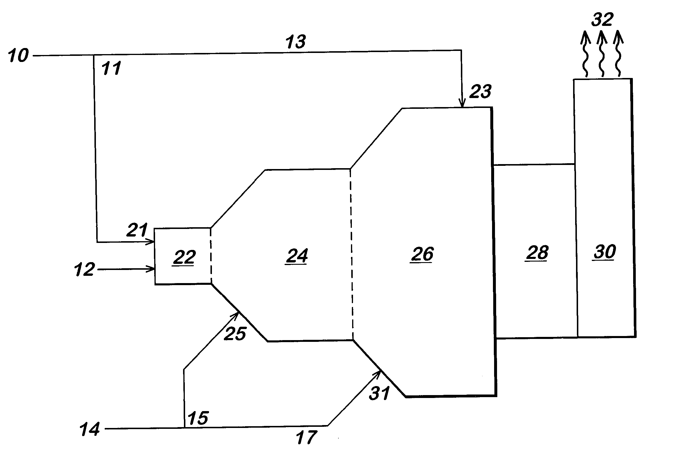
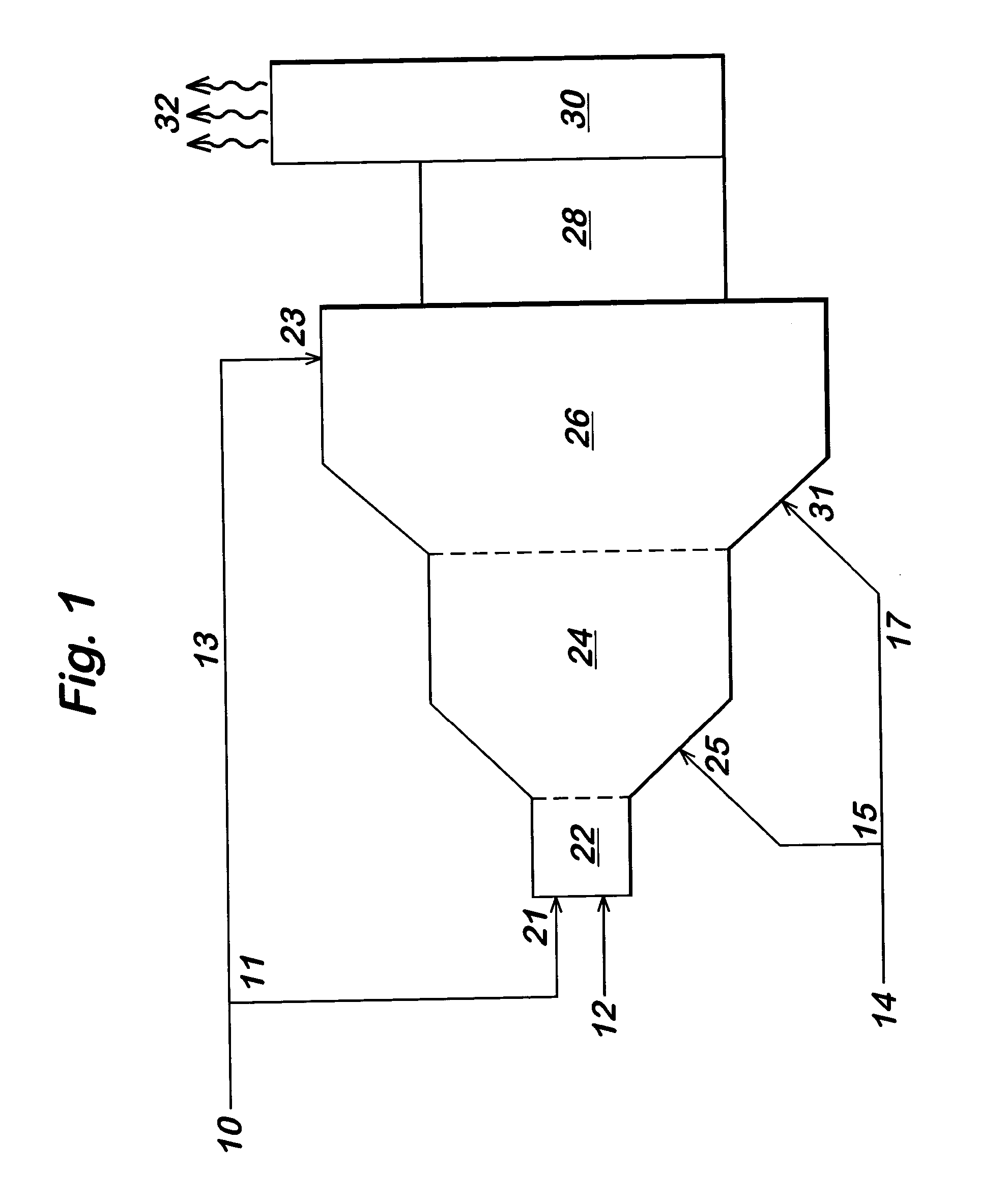
[0063] In an industrial chemical process for making acrylic acid from propylene feed, a horizontal three stage thermal oxidizer of the type illustrated in FIG. 1 was employed to dispose of waste streams. The furnace section of the thermal oxidizer (from addition point 21 to the end of waste destruction zone 26) was approximately 15.9 meters (52 feet) long. The inside diameter of primary waste destruction zone 24 was 1.8 meters (6 feet) and the inside diameter of secondary waste destruction zone 26 was 3.2 meters (10.5 feet). The base load NOx emissions for the thermal oxidizer were determined as follows:

[0064] Natural Gas from a commercial pipeline was used as the combustion fuel stream 12 and was injected into the primary combustion zone at a rate of 24, 525 liters / minute (866 scfm). Ambient temperature atmospheric air was used for oxidant stream 10. The airflow was injected into the primary combustion zone 22 at a rate of 310,387 liters / minute (10,960 scfm) and into the secondary ...


PUM


Abstract

The method of the present invention reduces the emissions of waste oxide gas produced within a thermal oxidizer by the use of a multizone waste thermal oxidizer, comprising at least one primary combustion zone and at least one downstream waste destruction zone. By performing the primary combustion of fuel prior to the destruction of at least a portion of the waste, it has been discovered that NOx emissions from the waste destruction process can be reduced economically and without significant loss of overall waste destruction efficiency.

Description

[0001] This invention relates to methods for reducing unwanted emissions in industrial processes. More specifically, this invention relates to methods for decreasing the production of waste oxide gases during thermal oxidation.[0002] Thermal oxidizers are often utilized to dispose of waste streams from industrial processes. In a typical thermal oxidizer, a waste stream and an oxidant are combined at high temperature in order to decompose the waste. If the waste stream is well mixed with the oxidant, and the waste is maintained at high temperature within the thermal oxidizer for a sufficient time period, waste destruction will occur through a combination of oxidation reactions. Often, it is also necessary to provide a fuel stream to the thermal oxidizer. The fuel stream is concurrently combusted in the thermal oxidizer to maintain the desired waste destruction temperature. In some instances, waste heat recovery equipment, such as a heat recovery steam boiler (HRSB), may also be incor...

Claims


Application Information

Patent Timeline
IPC IPC(8): B01D53/34B01D53/56F23G7/00F23G7/06
CPCF23G7/008F23G2202/105F23G7/065F23G7/00
Inventor DECOURCY, MICHAEL STANLEYPUGH, PATRICK KEVINPOOLE, LESLI BERNADETTE
Owner DECOURCY MICHAEL STANLEY
Why Eureka
Try Eureka