Aqueous viscoelastic fluid
a viscoelastic fluid and viscoelastic technology, applied in the field of fracturing fluids, can solve the problems of gel deformation, gel deformation at temperatures of about 240.degree. f, and is not possible to use quaternary ammonium salts
- Summary
- Abstract
- Description
- Claims
- Application Information
AI Technical Summary
Benefits of technology
Problems solved by technology
Method used
Image
Examples
example 2
Synthesis of Amide Carboxylates
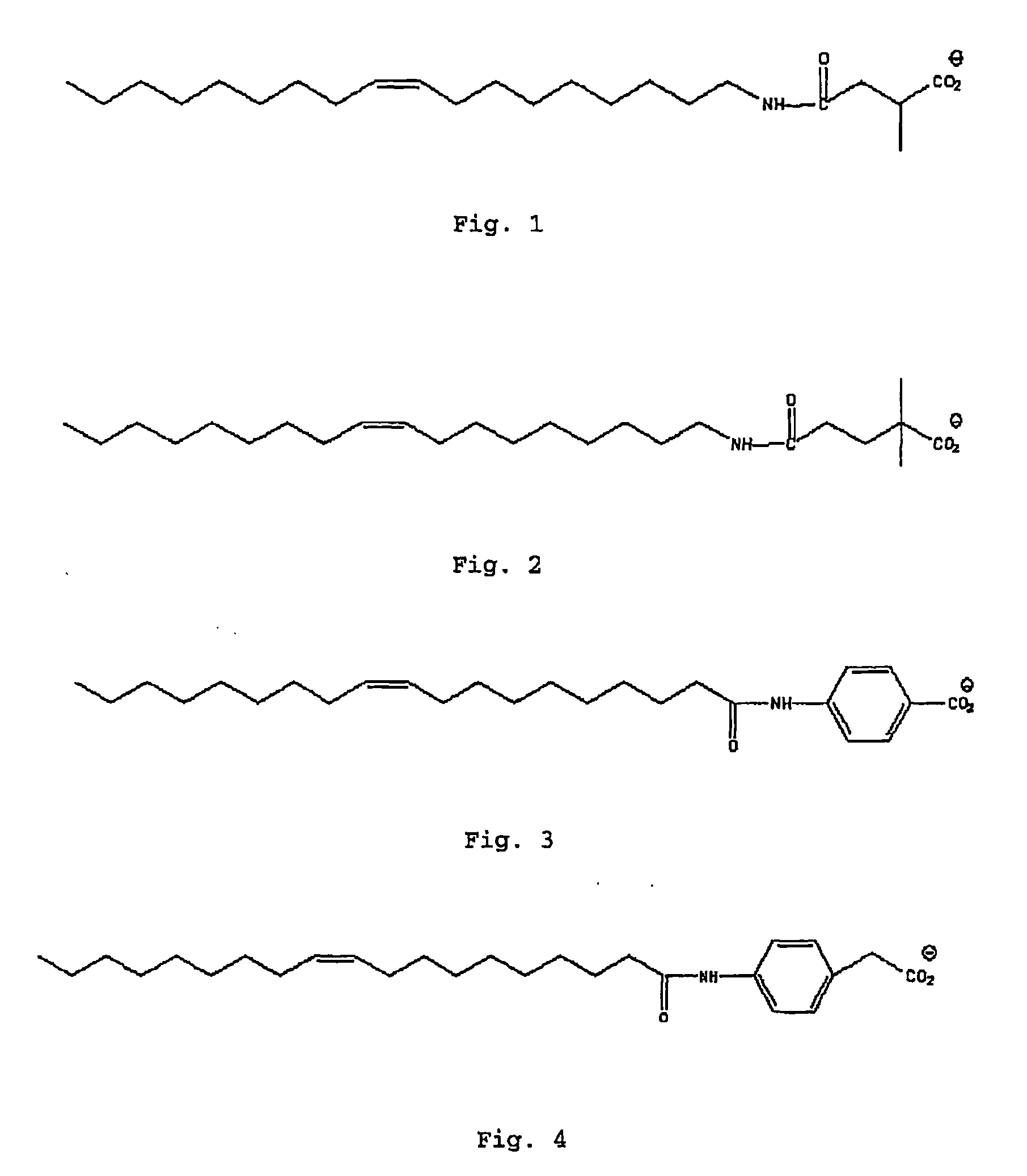
[0057] Oleyl amide succinic acid was synthesised using the following procedure. To a solution of 50 of oleyl amine in 100 ml THF was added 22 g, that is to say 1.2 mole equivalents, of succinic anhydride. The solution was then refluxed at a temperature of 68.degree. C. for 48 hours to ensure the complete reaction shown in the FIG. 6. THF was removed under vacuum and 50 ml of petroleum ether was added. The excess succinic anhydride not soluble in petroleum ether was removed by filtration on Whatman paper 43. The petroleum ether solution was cooled down and maintained at -10.degree. C. overnight using a refrigerated centrifuge. The white solid was then collected by centrifuging for 30 min at 9000 rpm. The product was washed with cold petroleum ether and dried under vacuum.
[0058] An equivalent procedure was used to prepare oleyl amide maleic acid form maleic acid and oleyl amide glutaric acid from glutaric anhydride.
example 3
Synthesis of Amide Carboxylates
[0059] The reagent erucyl acid chloride was prepared from erucic acid in the following manner. To 50 g erucic acid in 20 ml of THF was added 50 ml of thionyl chloride. The reaction was continued under reflux for 30 min and the solvent was removed under vacuum. A light brown liquid, the erucyl acid chloride product, was collected. To this liquid was added a solution / suspension of the sodium salt of beta-alanine in THF. The reaction shown in the FIG. 7 then took place under reflux for 24 hours. The solvent was removed under vacuum and petroleum ether was added. The solution was filtered on Whatman paper 43 and the filtrate solution was then cooled down to -10.degree. C. A light yellow solid product was collected.
example 4
Resistance of Erucyl Amide Succinate and Erucyl Amide Glutarate to High Temperatures
[0060] On FIG. 9 is plotted the viscosity, at a shear rate of 100 s.sup.-1, of an aqueous viscoelastic fluid according to the invention comprising 4 wt % of erucyl amide succinate and 4 wt % KCl, at a pH equal to 12, as a function of time, for the following temperatures: 130.degree. C., 150.degree. C., 170.degree. C. and 180.degree. C. A horizontal doted line is positioned at 50 cP on FIG. 9. It defines the limit at which the gel is considered to be insufficient for fracturing applications.
[0061] At 180.degree. C., the gel breaks in less than 1 hour. At 170.degree. C., the gel breaks in about 2 hours. At 150.degree. C. however, the viscosity of the gel breaks in about 4-6 hours to reach a viscosity of about 2 cP at about 15 hours. Finally, at 130.degree. C., the viscosity decreases slowly and is still in excess of 50 cP after 5 hours. After 25 hours, the viscosity is still greater than 20 cP.
[0062] A...
PUM
| Property | Measurement | Unit |
|---|---|---|
| Angle | aaaaa | aaaaa |
| Angle | aaaaa | aaaaa |
| Angle | aaaaa | aaaaa |
Abstract
Description
Claims
Application Information
 - R&D
- Intellectual Property
- Life Sciences
- Materials
- Tech Scout
- Unparalleled Data Quality
- Higher Quality Content
- 60% Fewer Hallucinations
Browse by: Latest US Patents, China's latest patents, Technical Efficacy Thesaurus, Application Domain, Technology Topic, Popular Technical Reports.
© 2025 PatSnap. All rights reserved.Legal|Privacy policy|Modern Slavery Act Transparency Statement|Sitemap|About US| Contact US: help@patsnap.com


