Device, method and materials for mobilizing substances into dentinal tubules in root canal treatment

a technology for dentinal tubules and root canals, applied in the field of devices, methods and materials for mobilizing substances into dentinal tubules in root canal treatment, can solve the problems of exacerbated infection and bone resorption, incongruous shape or size, and inability to achieve uniform shape or size,

Inactive Publication Date: 2004-05-27
RAMOT AT TEL AVIV UNIV LTD
View PDF10 Cites 123 Cited by
  • Summary
  • Abstract
  • Description
  • Claims
  • Application Information

AI Technical Summary

Problems solved by technology

Such bacteria and their products that have invaded the pulp within a root canal can migrate into the surrounding bone, resulting in a greatly exacerbated infection and bone resorption.
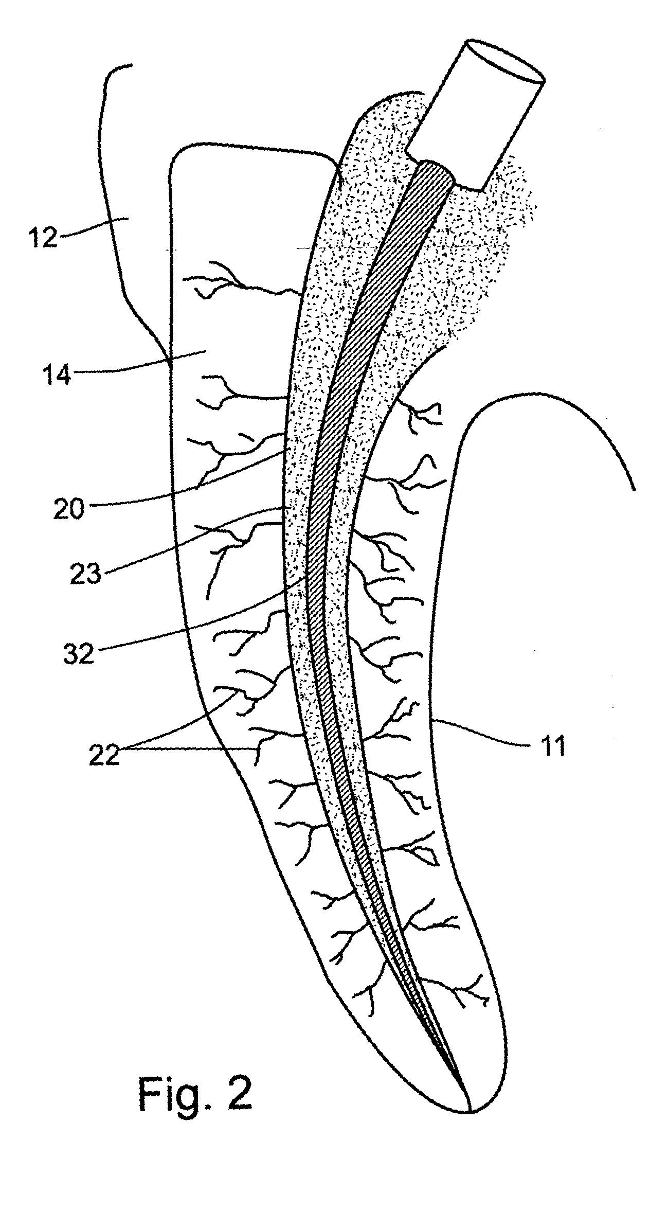
These tubules typically have a diameter of 2-5 micrometers and are not uniform in shape or size throughout the length of the root.
The treatment fails when infecting bacteria are not eliminated completely from both the root canal space and the dentinal tubules and irregular spaces.
According to the prior art, dental technology has found it difficult to completely eradicate all bacteria during a root canal treatment procedure.
The current technology does not appear to be capable of reliably disinfecting the canal wall in all cases Accordingly, it is now widely accepted that bacteria residing in dentinal tubules and irregular spaces is the primary cause of persistent endodontic infections.
Moreover, it has been shown repeatedly that such medicaments have limited ability to penetrate into and disinfect the dentinal tubules, (Siqueira J F, Uzeda M. Disinfection by Calcium hydroxide Pastes of Dentinal Tubules In

Method used


Image

  • Device, method and materials for mobilizing substances into dentinal tubules in root canal treatment
  • Device, method and materials for mobilizing substances into dentinal tubules in root canal treatment
  • Device, method and materials for mobilizing substances into dentinal tubules in root canal treatment

Examples


example 1

[0104] The following example serves as a testing model for determining the efficacy of three different disinfectant procedures, all using the same antiseptic agent.

[0105] The in vitro model for dentinal tubule infection of root canals originally described by Haapasalo and Orstavik (1987) was used in the present invention with some modifications. Extracted, intact bovine incisors were kept in 0.5% NaOCl overnight for surface disinfection. Five millimeters of the apical end and two-thirds of the crown were removed with a rotary diamond saw at 1000 rpm (Isomet plus precision saw, Buehler, Ill. U.S.A.) under cooling water. The root canal of the center piece was enlarged to 2 mm in diameter with a reamer bur (Zipperer, Munich Germany). The cementum was removed using a polish paper (Ecomet 3, variable speed grinder-polisher, Buehler Ill. U.S.A.) under cooling water, resulting in a center-holed root dentin piece of approximately 6 mm outer diameter. The root was then cut into slices of 4 m...

example 2

[0111] The following example serves as a testing model to determine the efficacy of hydroxyl diffusion into a dentinal wall when subjected to a low current electrical charge. Hydroxyl ions diffusion can be determined by measuring the pH of dentin at the outer root surface. (A. Nerwich, et al 1993).

[0112] Twelve extracted human permanent teeth with single canals were divided in two groups; experimental and control. Teeth were stored in unbuffered saline solution containing 0.05% sodium azide until used. All root canals were cleaned and shaped to a size 40 master file 1 mm from the anatomical apex. Irrigation during cleaning and shaping was carried out with 2.5% NaOCl. The canals were flushed with 1 ml of 17% EDTA which was left in place for one minute to remove the smear layer followed by a final irrigation with 5 ml of sodium hypochlorite. Cavities were drilled in the outer root surfaces of all teeth at midway between the cement enamel junction and the root apex. The cavities, 1.75 ...


PUM


Abstract

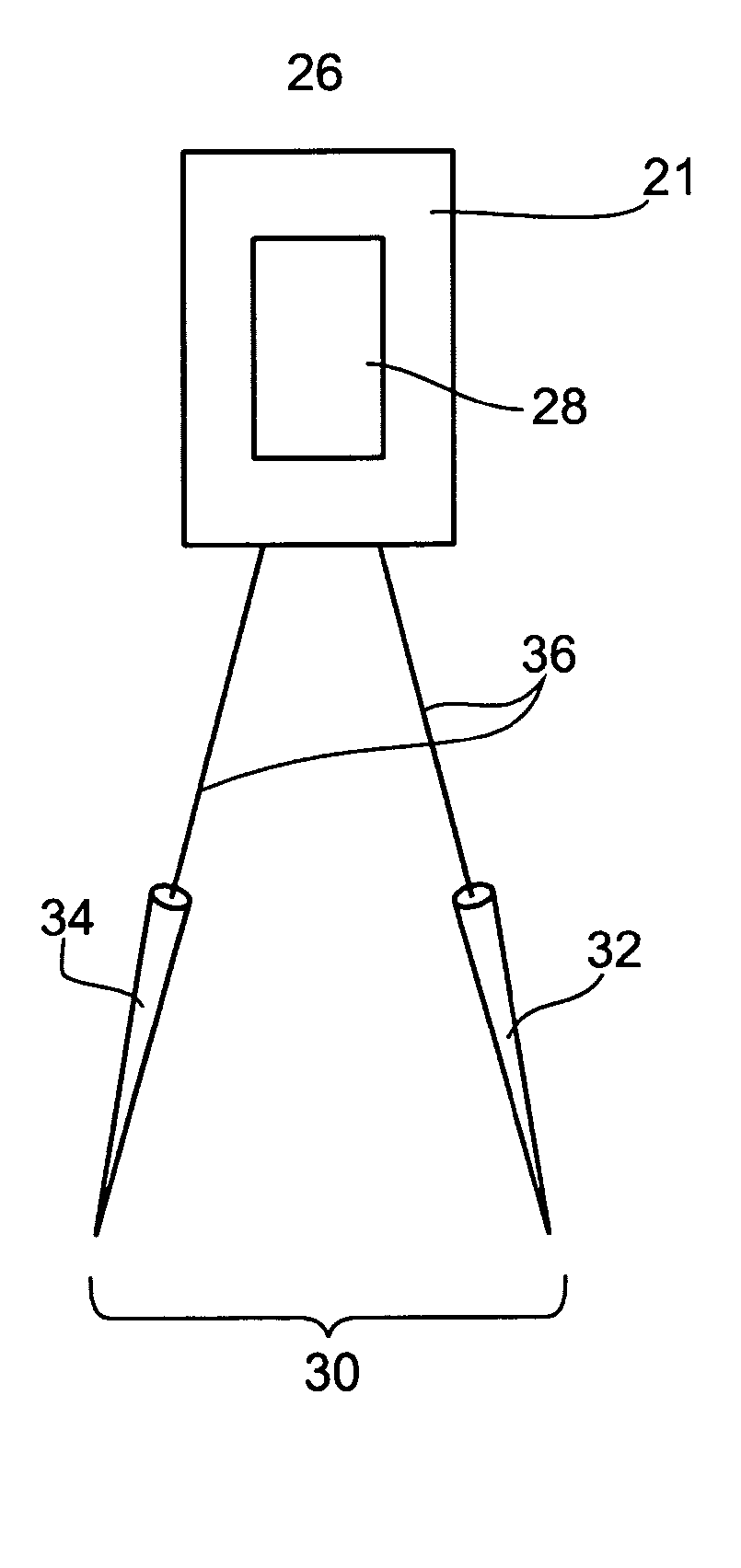
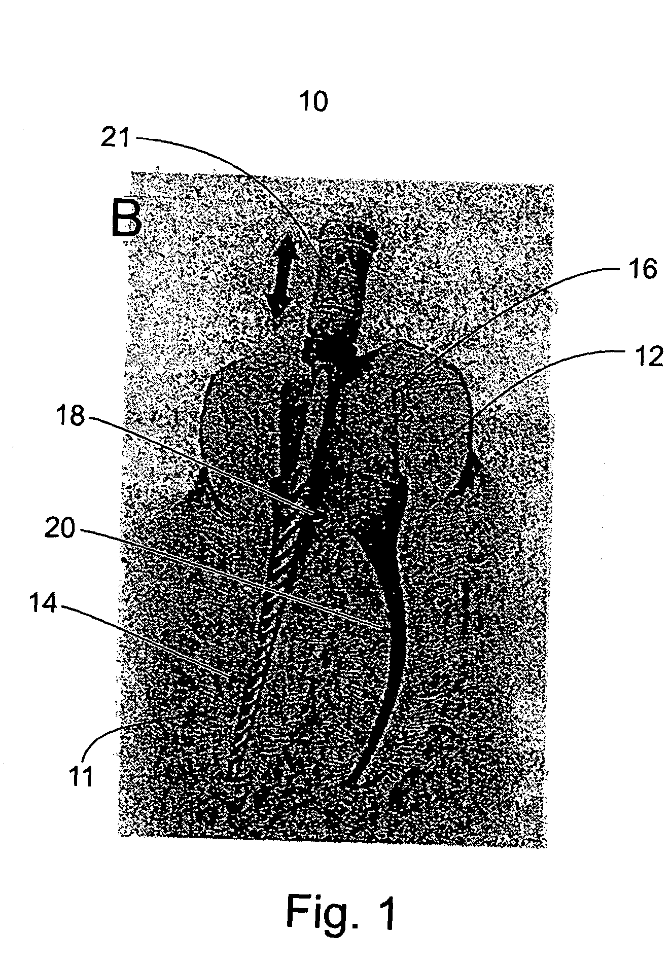
A device, method and composition of matter for use in mobilizing a medicament into the dentinal wall of a tooth comprising depositing a charged substance within a cavity of a tooth and subjecting the substance to an electric charge.

Description

FIELD AND BACKGROUND OF THE INVENTION[0001] The present invention relates to the field of dental treatment and, more particularly, to a device and method for mobilizing substances into tooth material.[0002] Anyone who has suffered a root canal procedure can attest to it being one of life's more unpleasant experiences. Root canal treatment is necessary whenever the tissue in a root canal is infected by bacteria. Such bacteria and their products that have invaded the pulp within a root canal can migrate into the surrounding bone, resulting in a greatly exacerbated infection and bone resorption.[0003] Therefore, the purpose of root canal treatment is to terminate the present infection by removing or killing bacteria that are within the root canal and to fill and seal the space in order to prevent reinfection.[0004] In the current state of dentistry, a root canal is disinfected by mechanical debridement of the canal wall and the application of an antiseptic substance within the canal to...

Claims


Application Information

Patent Timeline
IPC IPC(8): A61C5/02A61C19/06
CPCA61C19/06A61C5/02A61C5/40
Inventor WEISS, ERVIN IFUSS, ZVIASSOULINE, LEVI-SHAOULMIZRAHI, AMIR
Owner RAMOT AT TEL AVIV UNIV LTD
Why Eureka
Try Eureka