Nondestructive detection of reinforcing member degradation

a technology of reinforcing members and degradation, which is applied in the direction of fluid tightness measurement, instruments, mechanical means, etc., can solve the problems of weak tension, weak compression of concrete, and inability to withstand stress easily,

Inactive Publication Date: 2004-07-01
THE JOHN HOPKINS UNIV SCHOOL OF MEDICINE
View PDF9 Cites 53 Cited by
  • Summary
  • Abstract
  • Description
  • Claims
  • Application Information

AI Technical Summary

Problems solved by technology

However, like stone, concrete is strong in compression and weak in tension.
Plain concrete does not easily withstand stresses such as wind action, earthquakes, vibrations, and other bending forces, and is therefore unsuitable in many structural applications.
When re-bar degrades, it can expand to twice its initial volume, resulting in a large internal stress buildup that can lead to fracture and subsequent cracking of the concrete and catastrophic failure of the structure.
In this situation, the imaging of buried structures in the concrete is especially challenging due to the non-homogeneous nature of concrete that can have aggregate sizes ranging from, for example, 8 to 32 mm in diameter.
However, these techniques require highly trained personnel to collect the data and advanced tomography algorithms to reconstruct the buried structures.
This is beneficial since it may not always be possible to generate re-bar vibrations by contact in field conditions and since physical contact may damage the structure or re-bar being tested.
Absorption of a short pulse laser by a material results in localized thermal expansion and subsequent generation of broadband acoustic waves.

Method used


Image

  • Nondestructive detection of reinforcing member degradation
  • Nondestructive detection of reinforcing member degradation
  • Nondestructive detection of reinforcing member degradation

Examples


Embodiment Construction

)

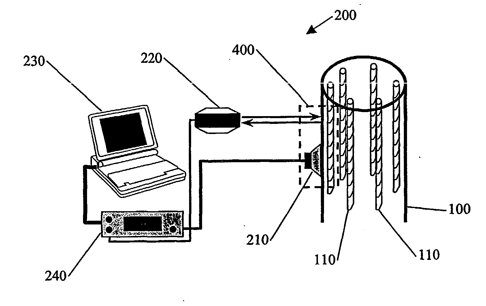
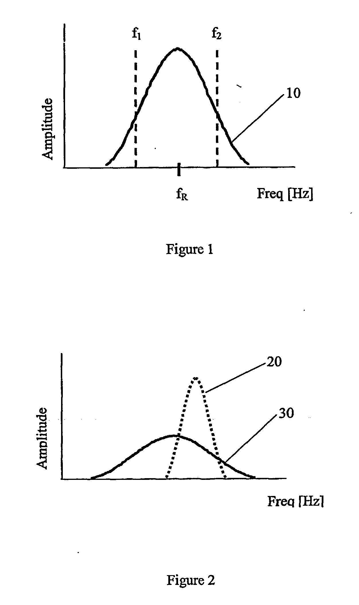
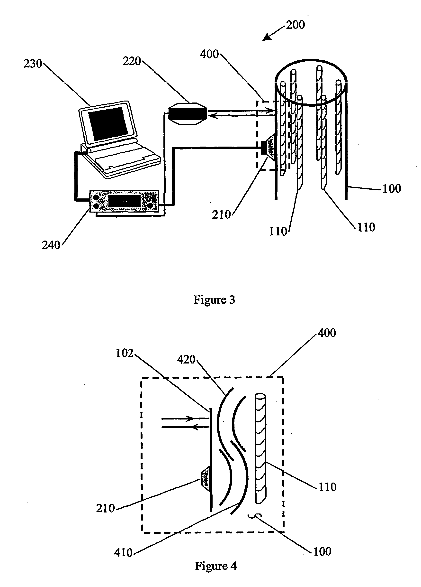
[0040] The purpose of the present invention is to develop a portable, non-imaging, non-destructive evaluation technique and device capable of detecting a degraded reinforcing member. The preferred embodiment of the present invention takes advantage of the acoustic resonance properties of re-bar in concrete in order to determine if significant re-bar degradation is present. The physical dimensions and elastic properties determine the resonant frequencies of the re-bar. The damping constant, Q, depends on the bonding of the re-bar to the concrete. Undegraded re-bar is expected to be well bonded to the concrete. However, as the re-bar degrades and expands, it effectively disbonds from the surrounding concrete, resulting in an increase of the damping constant Q. Thus, by devising a means to measure the damping constant Q of the re-bar, the bonding characteristics (and thereby the presence of degradation) can be determined. The two important components for a portable system are the effi...


PUM

PropertyMeasurementUnit
diameteraaaaaaaaaa
frequency contentaaaaaaaaaa
resonant frequenciesaaaaaaaaaa

Abstract

A nondestructive method of and apparatus for detecting degradation of reinforcing members embedded within a structure is disclosed. Degradation can arise from many sources, such as corrosion, fracture, cracking, fatigue, chemical reaction, etc. The device includes an inducing instrument(210) to induce a vibration of the reinforcing members (110)and a measuring device (220) to detect the vibration of the reinforcing members. The measurement is analyzed to detect the presence of reinforcing member degradation or reinforcing member-to-concrete bonding. The device may include a controller (230) to enhance the detection. The device may also include an amplifier (240) to further increase the energy in the waves imparted to the structure and the acoustic waves detected by the measuring instrument.(220)

Description

[0001] This application claims the benefit of U.S. Provisional Application No. 60 / 197,079, filed Apr. 13, 2000.[0002] 1. Field of the Invention[0003] This invention relates to a method of and apparatus for detecting the degradation of a reinforcing member. More specifically, this invention relates to nondestructive detection of degradation of a reinforcing member embedded within a structure.[0004] 2. Description of the Related Art[0005] Concrete is an artificial stone made from a mixture of water, aggregate (such as sand and gravel), and a binder (such as cement). Because of its potential for immense strength, its initial ability to adapt to virtually any form, and its resistance to fire, concrete has become one of the most common building materials in the world.[0006] However, like stone, concrete is strong in compression and weak in tension. Thus concrete is commonly strengthened by embedding reinforcing members ("re-bar") within it. Concrete containing embedded strengthening memb...

Claims


Application Information

Patent Timeline
Patent Type & Authority Applications(United States)
IPC IPC(8): G01H3/00G01H13/00G01H15/00G01M99/00G01N29/11G01N29/12G01N29/24
CPCG01H3/00G01H13/00G01H15/00G01M5/0008G01M5/0066G01N2291/0427G01N29/11G01N29/12G01N29/2418G01N2291/0231G01M5/0075
Inventor BLODGETT, DAVID W.VOJTECH, GEORGE L
Owner THE JOHN HOPKINS UNIV SCHOOL OF MEDICINE
Why Eureka
Try Eureka