
Heat exchange foam

a technology of heat exchange foam and foam material, which is applied in the direction of indirect heat exchangers, vacuum evaporation coatings, lighting and heating apparatus, etc., can solve the problems of difficult use in small devices and other applications, difficult to remove heat from small hot objects, and foam materials that do not utilize convective forces, etc., to achieve the effect of reducing the temperature gradient and increasing efficiency

Inactive Publication Date: 2004-07-01
UNIV OF VIRGINIA ALUMNI PATENTS FOUND
View PDF99 Cites 75 Cited by
  • Summary
  • Abstract
  • Description
  • Claims
  • Application Information

AI Technical Summary

Benefits of technology

[0021] Accordingly, an advantage of the present invention heat exchange apparatus and related method is that it transfers heat at an efficiency order of magnitude better than conventional conductive heat exchangers. The increased efficiency is a product of the decrease in the temperature gradient across the heat exchanger device.
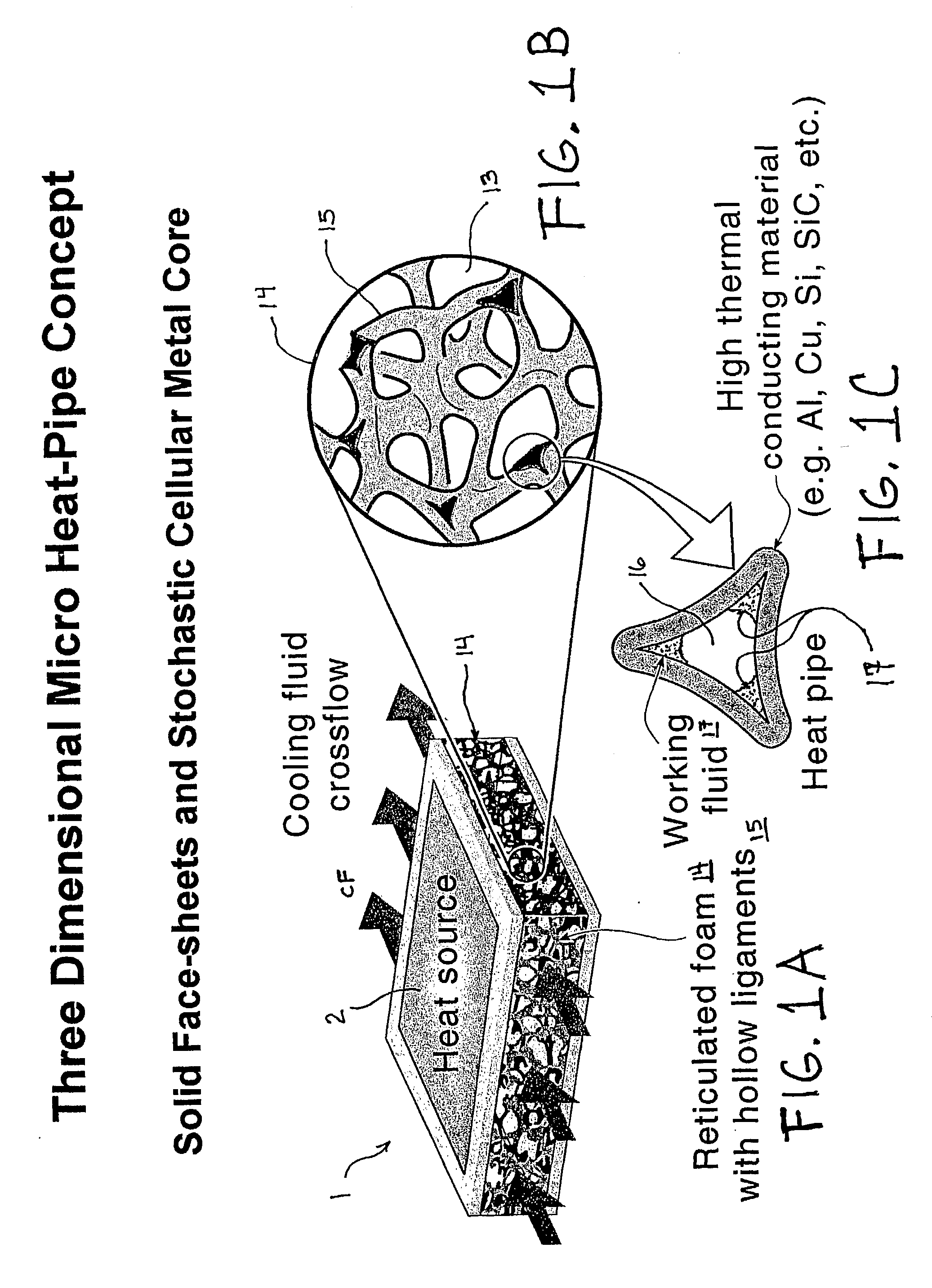
[0022] A further advantage of the present invention heat exchange apparatus and method is that allows for the hollow ligaments of an open or closed cell foam or interconnected cellular and / or truss network to act as the walls of a micro heat pipe. The foam or network must possess hollow ligaments in order utilize heat pipe heat transfer effects.
[0023] These and other objects, along with advantages and features of the invention disclosed herein, will be made more apparent from the description, drawings and claims that follow.
[0024] The foregoing and other objects, features and advantages of the present invention, as well as the invention itself, will be more fully understood from the following description of preferred embodiments, when read together with the accompanying drawings, in which:
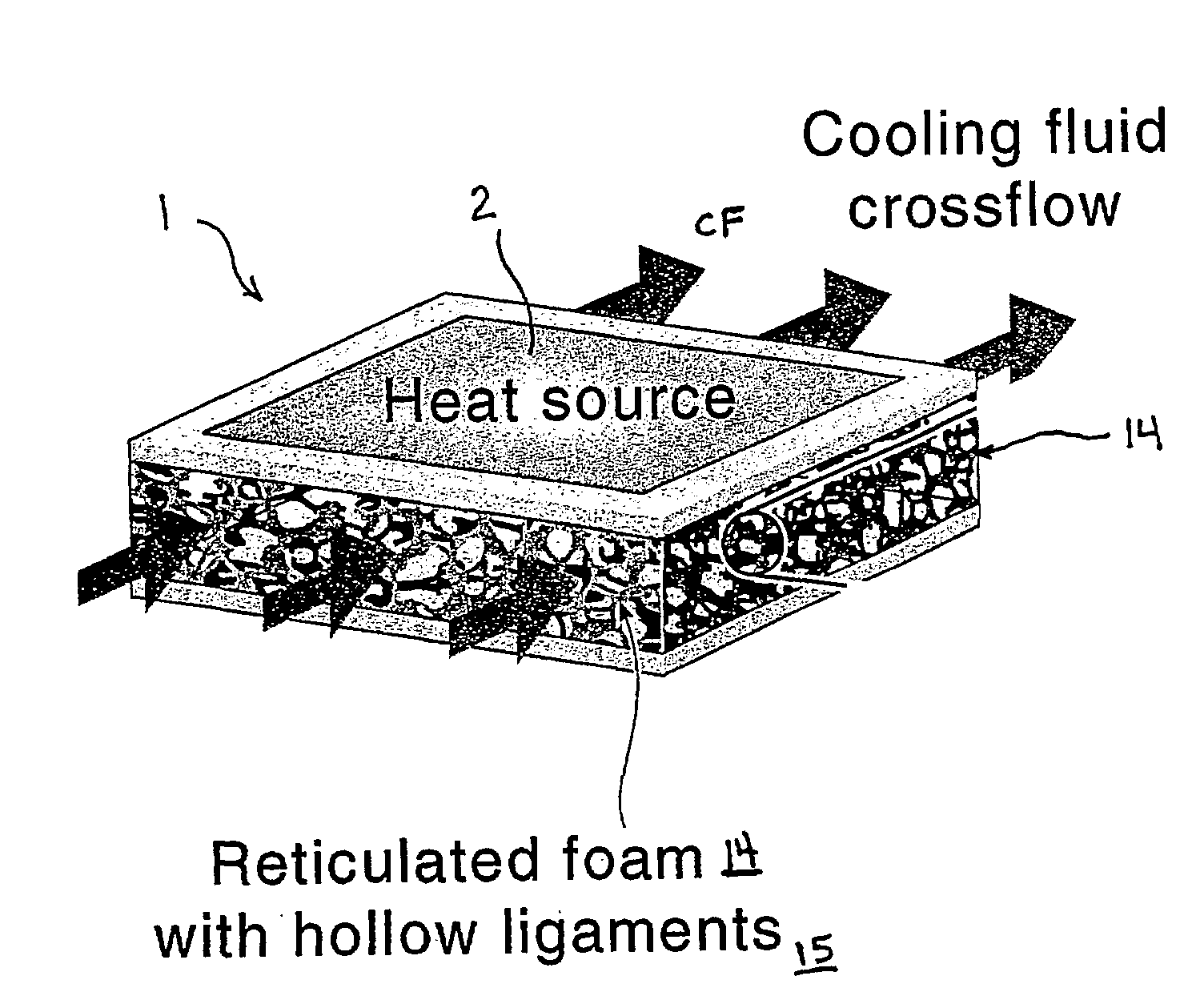
[0025] FIG. 1A shows a schematic representation of the present invention heat exchange apparatus.
[0026] FIG. 1B shows a schematic enlarged portion of the hollow ligaments of the foam as shown in FIG. 1A.

Problems solved by technology

However, these foam materials transport heat by conduction through solid ligaments.
Because the ligaments need to be interspersed with open porosity to allow efficient heat transfer to occur to a cooling fluid, heat removal from small hot objects is problematic.
The foam materials do not utilize convective heat transfer processes and can be difficult to use in small devices and other applications.
Though useful for a number of small scale applications, one and two dimensional micro heat pipes, like those claimed in U.S. Pat. No. 5,179,043 to Weichold, et al., U.S. Pat. No. 5,598,632 to Carmarda, et al., and U.S. Pat. No. 5,527,588 to Carmarda, et al., which are hereby incorporated by reference in their entirety herein, are limited in the art to one dimensional and two dimensional heat transfer.
They are also relatively heavy, unnecessarily rigid, and expensive to produce in full arrays.
Importantly, their ability to transfer heat by conduction and radiation is limited.
However, a vast majority of these types of processes have difficulty coating a solid ligament foam uniformly if the foam body is on the order of one or a few centimeters in thickness, or of greater thickness.
When producing heat exchangers of this size, it is difficult for these coating processes to penetrate the outer network of solid ligaments to uniformly coat the solid ligaments near the center of the foam body.
However, it is believed that their manufacturing process does not provide a mechanism to manufacture foams out of other conducting metals, alloys, ceramics or semiconductors.

Method used


Image

  • Heat exchange foam
  • Heat exchange foam
  • Heat exchange foam

Examples


example 2

Filling the Internal Volume with Working Fluid in a Vacuum Chamber

[0078] Seal all ends of the hollow ligaments, except for those through which working fluid will be introduced into the internal volume. Place foam in a vacuum chamber and evacuate the chamber. While the chamber is still evacuated, charge the internal volume with the appropriate quantity of working fluid, possibly through the use of tubing to deliver the working fluid to the internal volume. Seal off the remaining ends of the hollow ligaments to prevent escape of the working fluid.

example 3

Filling the Internal Volume with Working Fluid via Evaporation of the Fluid

[0079] Seal all ends of the hollow ligaments, except for those through which working fluid will be introduced into the internal volume. Charge the internal volume with a quantity of working fluid in excess of that amount desired to remain sealed in the internal volume, possibly by immersing the open ends of the hollow ligaments in a bath of the working fluid (working fluid will, for example, partially fill the internal volume via capillary action). Heat the working fluid to a temperature above its boiling point. The working fluid vapor will escape the internal volume and will evacuate the internal volume in the process. When the appropriate quantity of working fluid remains in the internal volume in liquid phase, seal off the remaining ends of the hollow ligaments.

[0080] By way of example, some preferred methods for sealing the ends of the hollow ligaments are (1) using an epoxy or other resin or glue to fill...

example 4

Production of a Periodic Interconnected Truss Network with Hollow Ligaments

[0081] FIGS. 10A-10C show a schematic representation of another preferred embodiment of the present invention wherein a interconnected network is provided having a periodic truss structure 24 made up of an array of intersecting structural support members whereby the structural support member form the hollow ligaments 22 . The interconnected networks include periodic truss structures 24 comprising intersecting structural support members that may be used to form the hollow ligaments 22 using the various deposition processes described above

[0082] The resultant hollow ligaments 22 that have a substantially circular cross section will require an internal wicking structure 25 to effect a heat pipe, as shown in FIGS. 10B-10C (whereas ligaments with acute corners do not require the additional wicking structure). The wicking structure has two functions. It is the vehicle and mechanism through which the working fluid r...


PUM

PropertyMeasurementUnit
Temperatureaaaaaaaaaa

Abstract

A heat exchanger (1) including a foam (14) having hollow ligaments (15) and an interstital volume (13).

Description

[0001] This application claims priority from U.S. Provisional Application Serial No. 60 / 219,149, filed on Jul. 14, 2000, entitled "Super Thermal Conducting Materials: Synthesis, Properties and Performance," the entire disclosure of which is hereby incorporated by reference herein.[0003] This invention relates to a method and apparatus for the efficient transfer of heat, and more specifically to a three-dimensional micro heat pipe utilizing a hollow ligament foam or interconnected network, and the method of manufacturing the same.BACKGROUND OF INVENTION[0004] Heat exchangers are widely used to facilitate the transfer of heat from regions of higher temperature to lower temperature. Metal or carbon foam structures are commonly employed in heat exchangers, wherein such structures have a relatively large surface area and are lightweight. The vast majority of foam heat exchangers is of the open cell or open pore variety, which allow the passing of fluid through the open foam. A lower temp...

Claims


Application Information

Patent Timeline
IPC IPC(8): C23C14/04F28D15/02F28D15/04F28F13/00
CPCC23C14/046C23C14/228F28D15/0233F28F13/003F28D15/0283F28D15/046F28D2015/0225F28D15/0275Y10S165/907Y02T50/60
Inventor QUEHEILLALT, DOUGLAS T.WADLEY, HAYDN N.G.KATSUMI, YASUSHI
Owner UNIV OF VIRGINIA ALUMNI PATENTS FOUND
Learn More