

Hard film and hard film-coated tool
- Summary
- Abstract
- Description
- Claims
- Application Information
AI Technical Summary
Benefits of technology
Problems solved by technology
Method used
Image

Examples
examples 2-4
, COMPARATIVE EXAMPLES 1-6
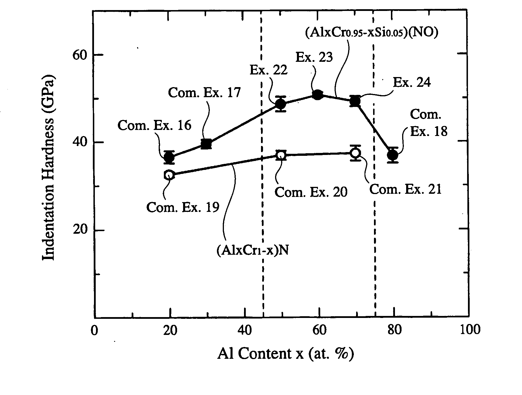
[0074] Hard films having compositions represented by (Al.sub.xCr.sub.1-x)(N.sub.0.95O.sub.0.05) were formed in the same manner as in Example 1. x was 0.2 in Comparative Example 1, 0.3 in Comparative Example 2, 0.5 in Example 2, 0.6 in Example 3, 0.7 in Example 4, and 0.8 in Comparative Example 3. Hard films having compositions represented by (Al.sub.xCr.sub.1-x)N were also formed in the same manner. x was 0.2 in Comparative Example 4, 0.5 in Comparative Example 5, and 0.7 in Comparative Example 6.
[0075] Using a micro-indentation hardness tester equipped with a triangular-pyramidal diamond indenter having a width tip angle of 1150, the indentation hardness of each hard film was measured under the conditions of the maximum load of 49 mN and a loading step of 4.9 mN / sec, with the maximum load kept for 1 second. The results are shown in FIG. 5. The indentation hardness shown in FIG. 5 is an average value of 10 measured values. FIG. 5 reveals that the hard films...
examples 5-9
, COMPARATIVE EXAMPLES 7-9
[0076] Hard films having compositions shown in Table 1 were formed on substrates of cemented carbide, high-speed steel and die steel in the same manner as in Example 1. Table 1 also shows the oxide layer thickness, indentation hardness, residual compression stress and elastic recovery ratio of each hard film. The thickness of the oxide layer was measured after keeping each hard film at 1100.degree. C. for 1 hour and 9 hours, respectively, in the air. The indentation hardness was measured in the same manner as in Example 2. The residual compression stress was calculated from the deformation of a thin plate. The elastic recovery ratio was determined by a nano-indentation method.
1 TABLE 1 Thickness (.mu.m) of Oxide Layer after Kept at Indentation Film Composition 1100.degree. C. for Hardness No. (atomic ratio) 1 hr. 9 hrs. (GPa) Example 5 (Al.sub.0.6Cr.sub.0.4)(N.sub.0.95O.sub.0.05) 0.1 0.6 48.8 Example 6 (Al.sub.0.6Cr.sub.0.4)(N.sub.0.92O.sub.0.08) 0.1 0.4 49...
examples 17-21
, COMPARATIVE EXAMPLES 13-15
[0086] Hard films having compositions shown in Table 3 were formed on a mirror-polished substrate of SNMN432 formed by cemented carbide containing 13.5% by mass of Co under the same film-forming conditions as in Example 10. Each hard film was kept at 1100.degree. C. for 1 hour and 9 hours, respectively, in the air, to measure the thickness of an oxide layer on each hard film. The results are shown in Table 3 together with those of Comparative Example 5. It is clear from Table 3 that the hard films of Examples 17-21 were not drastically oxidized, proving that they were excellent in a high-temperature oxidation resistance. On the other hand, the hard film of Comparative Example 13 containing 20 atomic % of Al was much more oxidized than those of Examples 17-21, proving that the former was poorer in a high-temperature oxidation resistance.
[0087] The cross section of each of the same hard films was mirror-polished by 0.1-.mu.m grinding diamond particles with ...
PUM
| Property | Measurement | Unit |
|---|---|---|
| Fraction | aaaaa | aaaaa |
| Fraction | aaaaa | aaaaa |
| Fraction | aaaaa | aaaaa |
Abstract
Description
Claims
Application Information