However, some technical and cost issues need to be addressed as well as the establishment of a
fuel distribution network before
fuel cells will be widely accepted into the commercial market.
Independent of the particular fuel
cell technology employed, poor distribution of either fuel or oxidant throughout the fuel cell can cause many problems, including poor
fuel conversion efficiency, "hot spots" within the fuel cell, decreased fuel cell life, and reduced
cell voltage.
Again, concentrations may drop because of the build up of reaction products (such as
liquid water as in the case of PEM fuel cells), or because of non-uniform operation of the cell's membrane.
Defects in the membrane can also cause low concentrations of needed reactants.
The
cell geometry within a fuel cell stack provides many flow paths for reactants to flow, which inherently creates flow distribution problems that can potentially cause inefficiencies or even damage to individual cells.
There is currently no mechanism to monitor or control individual fuel cells within a stack
system.
In particular, the existing PEM fuel cell stack systems experience problems associated with poor distribution of reactant fuel across the
membrane surface, which inherently causes a decrease in the membrane life cycle.
In addition, excess reactant flow is commonly used to correct for insufficient flow distribution across the
membrane surface, and this causes a decrease in fuel utilization efficiency.
Problems arise when the generated
water vapor condenses onto the channel surfaces thereby blocking or restricting the flow through the channel, and the amount of
hydrogen reacting with the catalyst.
When this happens, the associated cell will perform poorly (generate
low voltage and current) and cause the cell to overheat locally at the misbehaved channel.
Damage can result if the stack is operated for too long at these conditions.
This makes the design of the channel and manifold geometry difficult, especially if the
system is to be used under a wide range of operating conditions.
Additionally, the aforementioned situations can go unnoticed by typical control strategies that only monitor the overall stack
voltage.
However, for automotive applications, for example, the size and weight of additional cells and the stack performance at higher
current density conditions can have a significant
impact on cost.
In Kazmin's model the minimum stack operating efficiency that provides acceptable economics is mainly affected by the fuel cost and cell efficiency.
Furthermore,
maximum efficiency can only be achieved through effective thermal and water management, and proper gas flow distribution to each cell within the stack.
More importantly, as shown by Lee, inadequate distribution of fuel cell-to-cell can cause irreparable damage to the MEA and lead to cell failure.
In addition, by using the micro-systems manufacturing techniques the additional
capital cost for the micro-valves could be low.
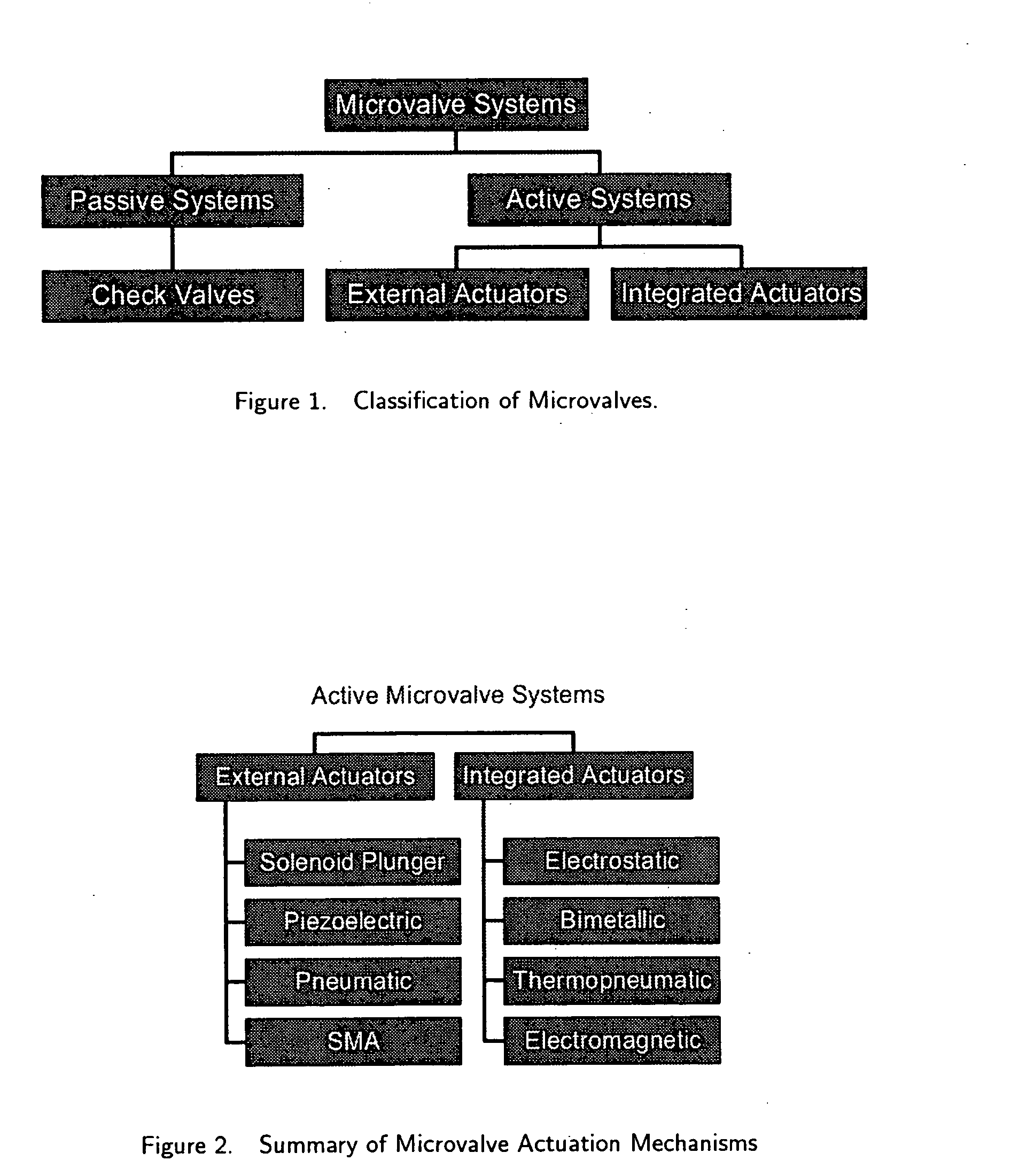
Each type of mechanism offers advantages and disadvantages in terms of cost, complexity, speed, performance, and reliability.
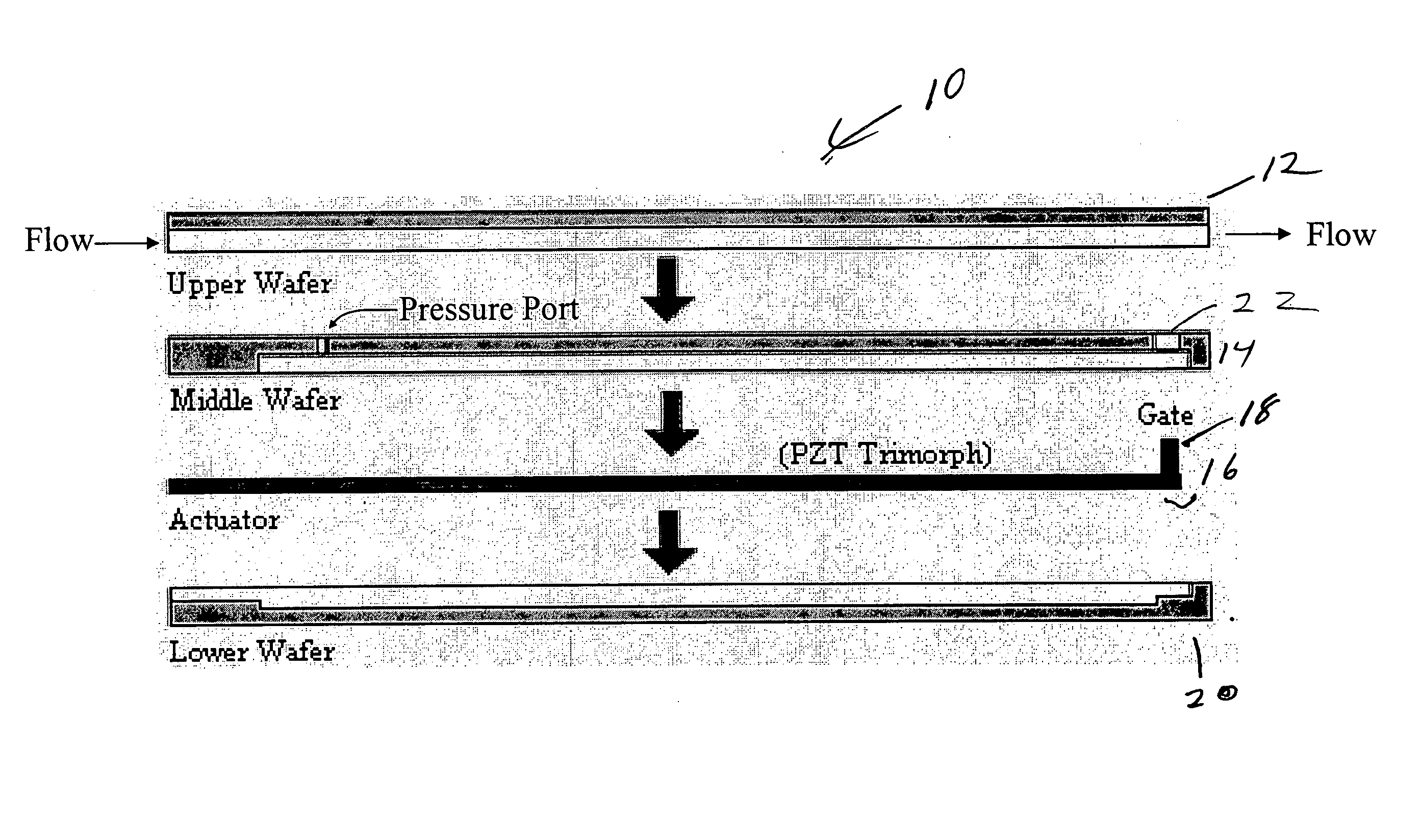
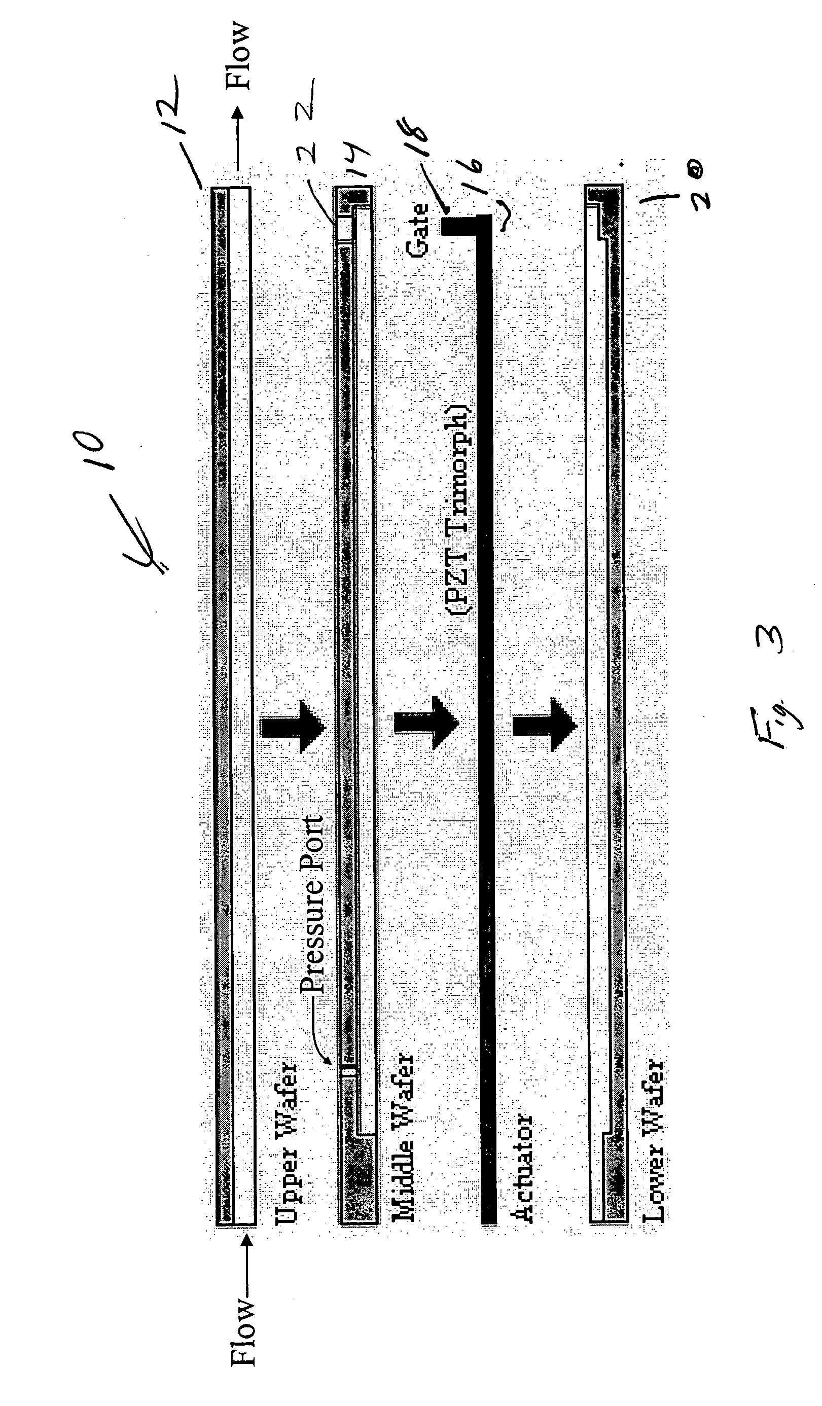
The commercially available valves will not meet all of the requirements, necessitating a custom valve design.
However, commercially available microvalves do not meet the unique requirements of the fuel cell application.
Commercial microvalves have larger dimensions than the required design and their
operating temperature limits are not in the range of fuel cell microvalve requirements and some of microvalves are not suitable for hydrogen environment, necessitating a custom design.
The disadvantages are few, including the inability to completely clamp off the flow (acceptable for this application), and being potentially fragile, which can be mitigated to some degree by design.

