Optical recording medium

a recording medium and optical recording technology, applied in the field can solve the problems of difficult layer formation, prone to cross-erasing of data, and the durability of optical recording mediums when data are repeated reproduced

Inactive Publication Date: 2004-07-29
TDK CORPARATION
View PDF26 Cites 33 Cited by
  • Summary
  • Abstract
  • Description
  • Claims
  • Application Information

AI Technical Summary

Problems solved by technology

As a result, it becomes difficult to form a layer such as a recording layer on the light transmission layer as is done in conventional optical recording media such as the CD and DVD.
However, in the case where a recording layer is formed of a phase change material having a high crystallization velocity, since a phase change material in an amorphous phase crystallizes in an extremely short time when a record mark is to be erased, the durability of the optical recording medium when data are reproduced repeatedly declines and when data are recorded in or data are erased from a particular track, data recorded in neighboring tracks are erased, whereby cross-erasing of data is apt to occur.
Since these problems become pronounced as the power of the laser beam per unit area increases, they become particularly serious in a next-generation type optical recording medium.
However, when the recording layer 14 is too thin, the difference in the optical constants between before and after data recording becomes small and a reproduced signal having a high level (C / N ratio) cannot be obtained.
In the case where the thickness of the heat radiation layer 16 is thinner than 50 nm, sufficient heat radiation characteristics cannot be obtained and, on the other hand, in the case where the thickness of the heat radiation layer 16 exceeds 150 nm, it takes much time to form the heat radiation layer 16, thereby lowering the productivity of the optical recording medium 10 and giving rise to a risk of cracks being generated in the heat radiation layer 16 due to internal stress.

Method used


Image

  • Optical recording medium
  • Optical recording medium
  • Optical recording medium

Examples


working example 1

[0092] An optical recording medium sample # 1 was fabricated in the following manner.

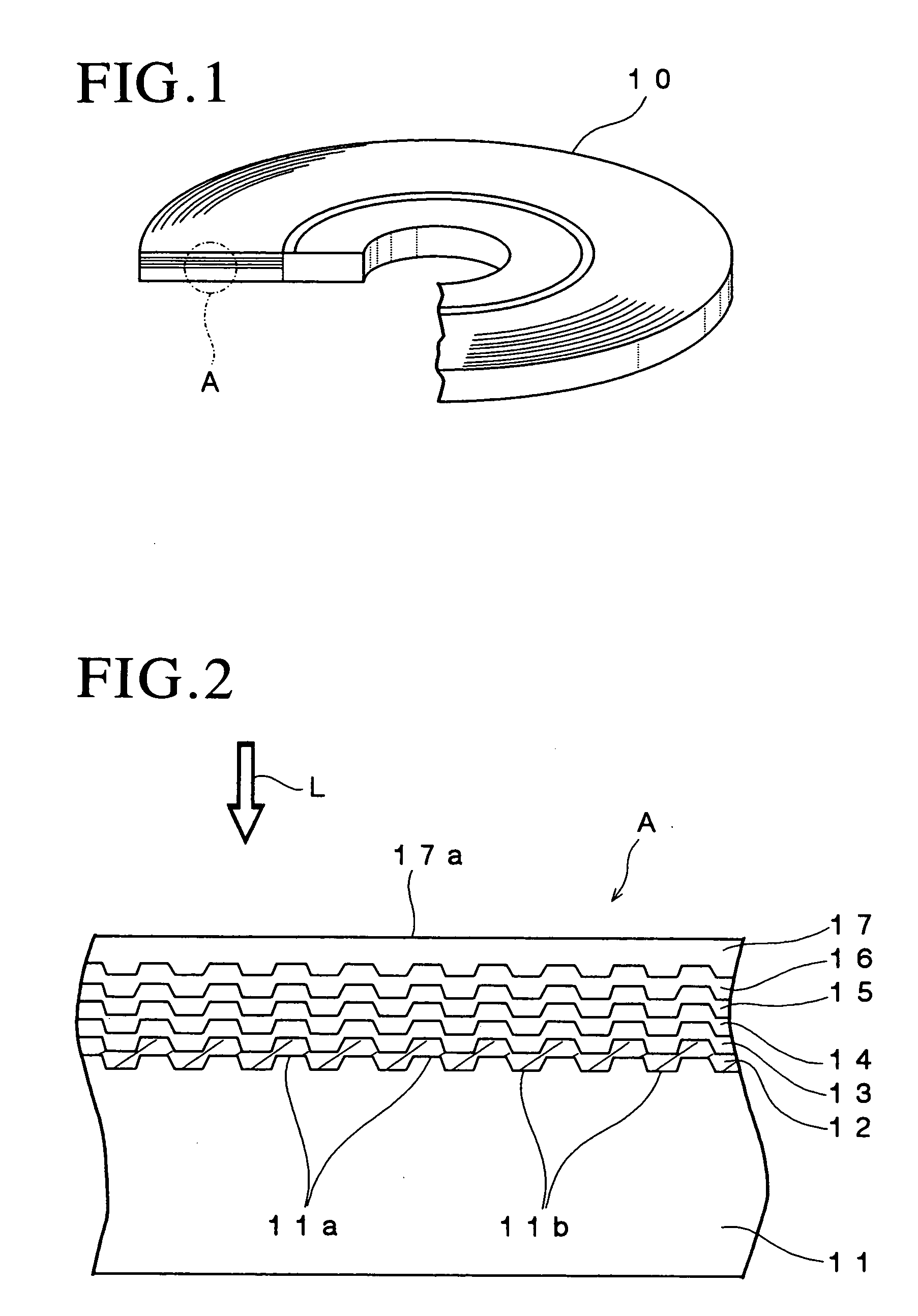
[0093] A substrate of polycarbonate having a thickness of 1.1 mm and a diameter of 120 mm and formed with grooves and lands on the surface thereof was first fabricated by an injection molding process so that the track pitch (groove pitch) was equal to 0.32 .mu.m. The depth of the groove was 25 nm.

[0094] Then, the substrate was set on a sputtering apparatus and a reflective layer consisting of an alloy of Ag, Pd and Cu and having a thickness of 100 nm, a second dielectric layer consisting of a mixture of ZnS and SiO.sub.2 and having a thickness of 12 nm, a recording layer consisting of Ge.sub.0.06Sb.sub.0.76Te.sub.0.18 and having a thickness of 12 nm, a first dielectric layer consisting of the mixture of ZnS and SiO.sub.2 and having a thickness of 30 nm and a heat radiation layer containing 90 atomic % of more of aluminum nitride and having a thickness of 100 nm were sequentially formed on the surfac...

working example 2

[0109] Each of the optical recording medium sample #1, the optical recording medium sample #2, the optical recording medium comparative sample #1 and the optical recording medium comparative sample #2 was set in the above mentioned optical recording medium evaluation apparatus and a laser beam having a wavelength .lambda. of 405 nm whose power was set to the recording power at which the clock jitter of a reproduced signal was lowest onto the recording layer of each sample to record an 8T signal in a predetermined track of the recording layer and the thus recorded 8T signal was then overwritten nine times.

[0110] Then, the 8T signal recorded in the predetermined track of the recording layer of each of the optical recording medium sample #1, the optical recording medium sample #2, the optical recording medium comparative sample #1 and the optical recording medium comparative sample #2 was reproduced and the carrier level C1 of the reproduced signal was measured.

[0111] Further, a laser ...

working example 3

[0118] Optical recording medium samples #1-1 to #1-6 were fabricated in the manner of fabricating the optical recording medium sample #1, optical recording medium samples #2-1 to #2-6 were fabricated in the manner of fabricating the optical recording sample #2 and optical recording medium comparative samples #1-1 to #1-6 were fabricated in the manner of fabricating the optical recording medium comparative sample #1, except that each support substrate was formed to have a different groove pitch (track pitch) in the range of 0.26 .mu.m to 0.36 .mu.m.

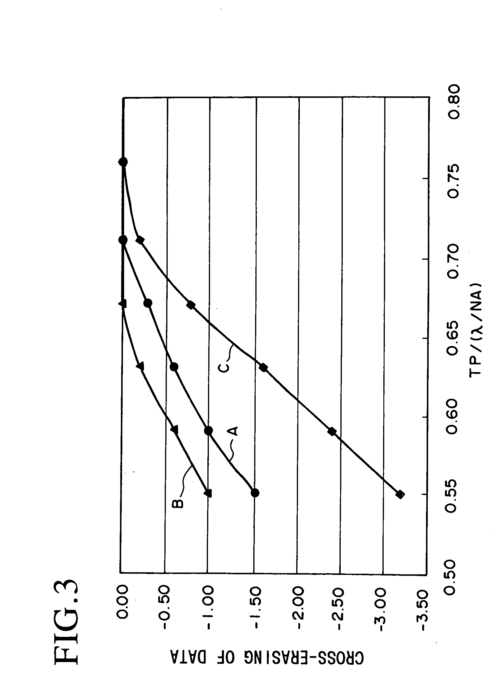
[0119] Then, each of the optical recording medium samples #1-1 to #1-6, the optical recording medium samples #2-1 to #2-6 and the optical recording medium comparative samples #1-1 to #1-6 was set in the above mentioned optical recording medium evaluation apparatus and similarly to Working Example 2, cross-erasing CE of data was measured in each sample, thereby measuring the relationship between cross-erasing CE of data and TP / (.lambda. / NA)...


PUM

PropertyMeasurementUnit
thicknessaaaaaaaaaa
thicknessaaaaaaaaaa
outer diameteraaaaaaaaaa

Abstract

An optical recording medium includes a recording layer in which a record mark can be formed by projecting a laser beam thereonto, a first dielectric layer disposed on the side of a light incidence plane with respect to the recording layer, a second dielectric layer disposed on the opposite side to the light incidence plane with respect to the recording layer, a heat radiation layer disposed on the side of the light incidence plane with respect to the first dielectric layer and a reflective layer disposed on the opposite side to the light incidence plane with respect to the second dielectric layer, the recording layer containing a phase change material represented by a general formula: (SbxTe+x)+y My wherein M is an element other than Sb and Te, the first dielectric layer containing a mixture of ZnS and SiO2, the reflective layer containing Ag or alloy containing 90 atomic % or more of Ag, and the heat radiation layer containing 90 atomic % or more of aluminum nitride. According to the present invention, it is possible to provide a data rewritable type optical recording medium whose durability is improved when data are reproduced repeatedly, which can suppress cross-erasing of data when data are to be recorded or erased and in which data can be recorded with high sensitivity at a high velocity.

Description

[0001] The present invention relates to an optical recording medium and, particularly, to a data rewritable type optical recording medium whose durability when data were reproduced repeatedly is improved when data are reproduced, which can suppress cross-erasing of data when data are to be recorded or erased and in which data can be recorded with high sensitivity at a high velocity.DESCRIPTION OF THE PRIOR ART[0002] Optical recording media such as the CD, DVD and the like have been widely used as recording media for recording digital data. These optical recording media can be roughly classified into optical recording media such as the CD-ROM and the DVD-ROM that do not enable writing and rewriting of data (ROM type optical recording media), optical recording media such as the CD-R and DVD-R that enable writing but not rewriting of data (write-once type optical recording media), and optical recording media such as the CD-RW and DVD-RW that enable rewriting of data (data rewritable ty...

Claims


Application Information

Patent Timeline
Patent Type & Authority Applications(United States)
IPC IPC(8): B41M5/26G11B7/007G11B7/24G11B7/24056G11B7/24079G11B7/243G11B7/2433G11B7/254G11B7/257G11B7/258G11B7/2585G11B7/259
CPCG11B7/00454G11B7/257G11B7/243G11B7/24079
Inventor KATO, TATSUYASHINGAI, HIROSHIKOBAYASHI, TATSUHIROHIRATA, HIDEKI
Owner TDK CORPARATION
Why Eureka
Try Eureka