Aluminium-wettable porous ceramic material

a porous ceramic material and wettable technology, applied in the direction of isotope separation, dispersed particle separation, chemistry apparatus and processes, etc., can solve the problems of many difficulties encountered in the production of refractory boride coatings, and achieve energy saving, reduced cell voltage, and reduced cost

Inactive Publication Date: 2004-08-05
DE NORA VITTORIO
View PDF5 Cites 9 Cited by
  • Summary
  • Abstract
  • Description
  • Claims
  • Application Information

AI Technical Summary

Benefits of technology

0064] In a variation, a retrofitted cell without an aluminium collection groove may operate with a shallow aluminium cathodic pool with little motion of molten aluminium in the shallow cathodic pool. Consequently, the inter-electrode distance may also be reduced which leads to a reduction of the cell voltage and energy savings. Furthermore, compared to conventional deep pool cells, a smaller amount of molten aluminium is needed to operate the cell which substantially reduces the costs involved with immobilising large aluminium stocks in aluminium production plants.
0065] Nevertheless, these aluminium-wetted cathode linings can also be used in deep pool cells operating with a frozen electrolyte ledge and / or an electrolyte crust above the molten electrolyte. Furthermore, one or more large aluminium-wetted conductive plates according to the invention made from a low density openly porous or reticulated ceramic structure may be put into the aluminium pool so that the plates float at the surface of the aluminium pool to restrain aluminium motion and stabilise the aluminium pool. Thus, use of stabiliser plates in a deep aluminium pool permits a reduction of the inter-electrode distance.

Problems solved by technology

Many difficulties were encountered in producing refractory boride coatings which meet up to the rigorous conditions in an aluminium electrowinning cell.

Method used


Image

  • Aluminium-wettable porous ceramic material
  • Aluminium-wettable porous ceramic material
  • Aluminium-wettable porous ceramic material

Examples


example 2

[0077] An aluminium-wettable ceramic structure was made of a mixture of material inert and resistant to molten aluminium, i.e. alumina and titania, and aluminium-wettable material, i.e. copper oxide. The ceramic structure was prepared by coating a polyurethane foam with a slurry of ceramic particles followed by a heat treatment.

[0078] The slurry of ceramic material consisted of a suspension of 40 g particulate Al.sub.2O.sub.3 with an average particle size of 10 to 20 micron, 2.5 g of particulate CuO with a particle size of less than about 45 micron, 2.5 g of particulate TiO.sub.2 with a particle size of less than about 45 micron in a colloidal alumina carrier consisting of 93 g deionised water and 6.6 g colloidal alumina particles with a colloidal particle size of about 10 to 30 nanometer.

[0079] A polyurethane foam having 10 to 20 pores per inch (equivalent to about 4 to 8 pores per centimetre) was dipped into the slurry and dried in air at 400 to 50.degree. C. for 20 to 30 minutes....

example 3

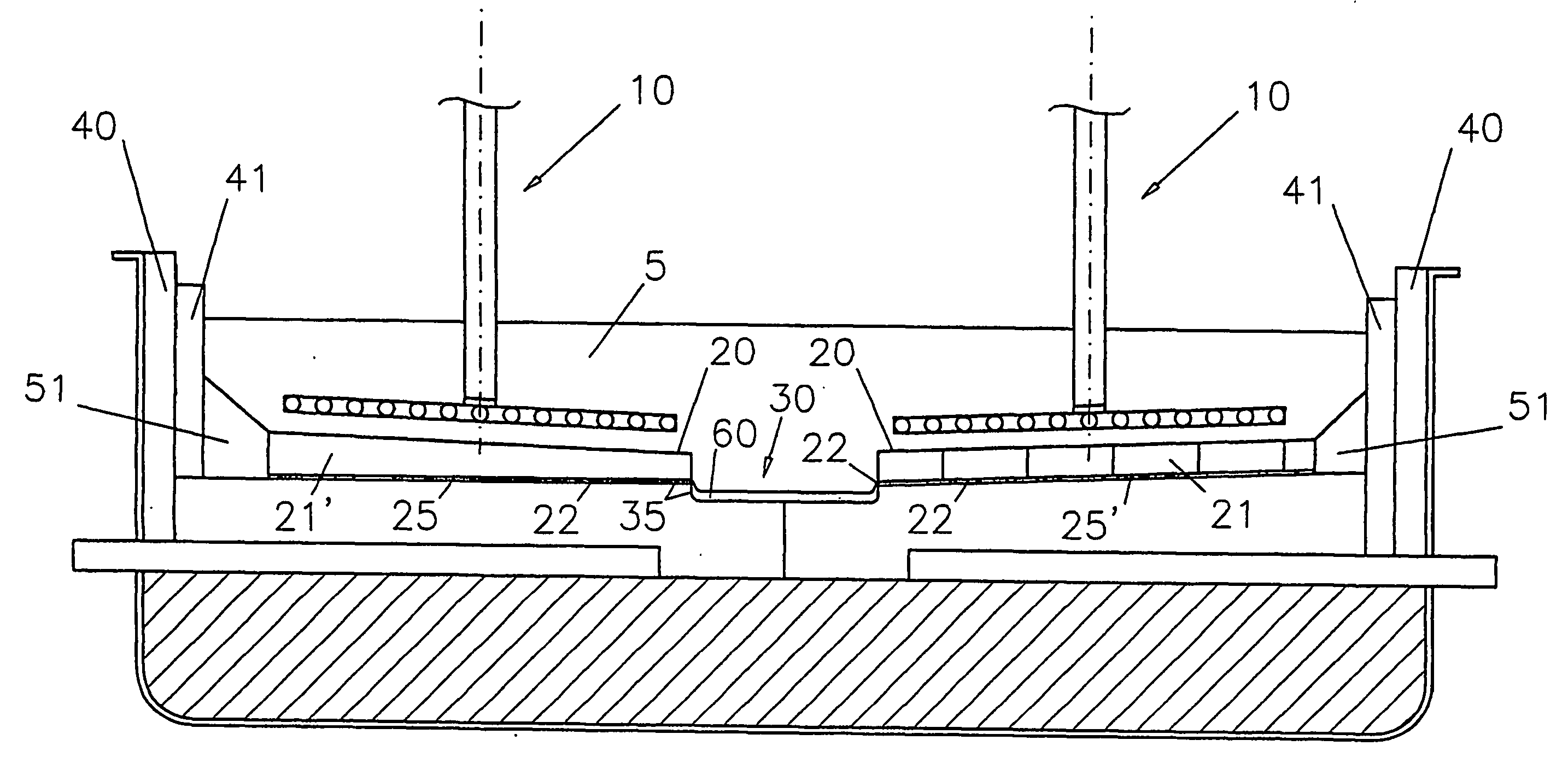
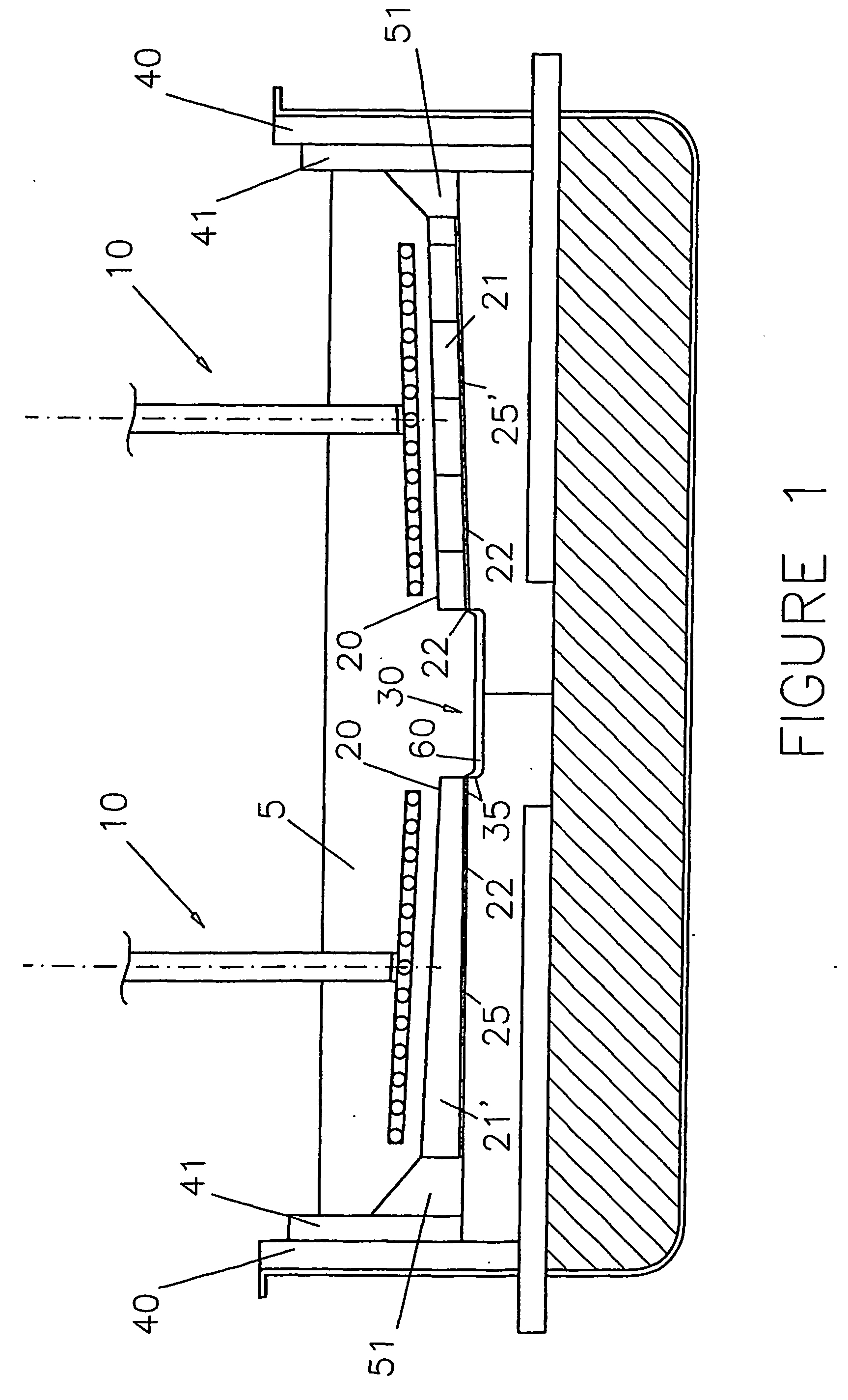
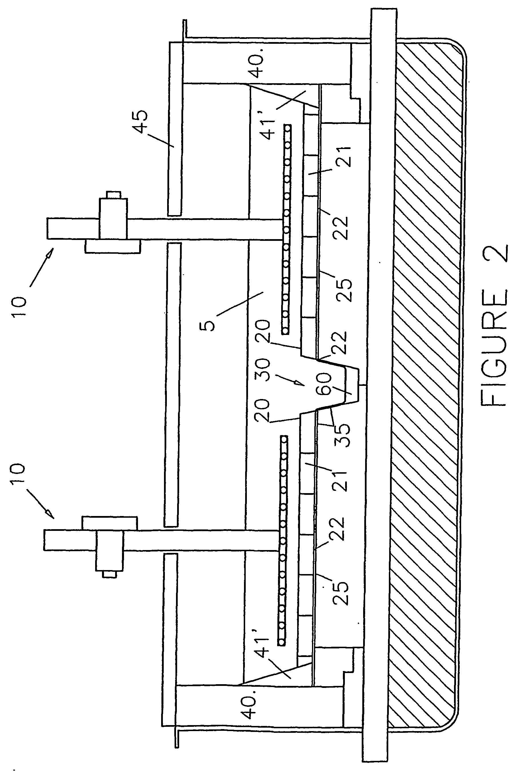
[0084] An aluminium-wettable openly porous ceramic structure as in Example 1 was tested as cathodic material for aluminium production.

[0085] The aluminium-wettable ceramic structure was placed on the bottom of a graphite receptacle having an inner diameter of 85 mm. The structure was covered with 120 g aluminium. The receptacle and its content was heated at a rate of 120.degree. C. / hour. At a temperature of 700.degree. C., the aluminium had formed an aluminium pool on which the ceramic structure was floating. The temperature was further increased to about 850.degree. C. and then maintained for 4 hours so that the molten aluminium completely aluminised and wet the ceramic structure.

[0086] After aluminisation, an amount of 1.5 kg electrolytic molten bath consisting of 68 weight % cryolite, 28 weight % aluminium fluoride and 4 weight % dissolved alumina was poured into the receptacle on top of the aluminium pool and aluminium-wetted ceramic structure. A carbon anode was dipped into the...

example 4

[0089] An openly porous silicon carbide structure (30 pores per inch which is equivalent to about 12 pores per centimetre) was rendered aluminium-wettable by coating it with a slurry-applied layer.

[0090] The slurry consisted of 75 g surface oxidised iron particles (-325 mesh), 75 g Silica sol Nyacol 830 (a milky aqueous liquid containing 32 weight % colloidal silicon hydroxide that is converted into silica upon heat treatment) and 0.35 g of an aqueous solution containing 15% PVA (polyvinyl alcohol) that was used to adjust the viscosity of the slurry.

[0091] The openly porous structure was dipped onto the slurry and then dried for 30 min. at 60.degree. C. The impregnated porous structure contained 0.278 g / cm.sup.3 of dried slurry including 0.214 g / cM.sup.3 surface oxidised iron particles.

[0092] The resulting structure was aluminium-wettable and suitable to be wetted by aluminium before use or in-situ when used for example as a cathode.

[0093] The aluminium-wettable porous structure was...


PUM

PropertyMeasurementUnit
temperaturesaaaaaaaaaa
temperatureaaaaaaaaaa

Abstract

A material, for instance used as an aluminium-wettable component (21,21', 41,41', 51), in particular of a cell for the electrowinning of aluminium (60), comprises an openly porous or reticulated ceramic structure whose surface during use is exposed to and wetted by molten aluminium. The structure is made of ceramic material inert and resistant to molten aluminium, such as alumina, and an aluminium-wettable material that comprises metal oxide and/or partly oxidised metal, in particular of manganese, iron, cobalt, nickel, copper or zinc, which is/are reactable with molten aluminium to form a surface layer containing alumina, aluminium and metal derived from the metal oxide and/or partly oxidised metal. The ceramic structure comprises a coating of the aluminium-wettable material on the inert and resistant ceramic material, or is made of a mixture of the inert and resistant material and of the aluminium-wettable ceramic material. The aluminium-wetted component is suitable for use as a cathode (21,21'), as a sidewall (41,41') or as another component (51) which during use is exposed to molten aluminium (60) and/or electrolyte (5), or another oxidising and/or corrosive media at high temperature.

Description

[0001] The invention relates to a ceramic material which can be utilised for the manufacture of aluminium-wettable and aluminium-wetted ceramic components, in particular for use in aluminium production, for example as cathodes, sidewalls and other cell components which during use are exposed to molten aluminium, electrolyte and / or corrosive gases.[0002] Aluminium is produced conventionally by the Hall-Heroult process, by the electrolysis of alumina dissolved in cryolite-based molten electrolytes at temperatures up to around 950.degree. C. A Hall-Heroult reduction cell typically has a steel shell provided with an insulating lining of refractory material, which in turn has a lining of carbon which contacts the molten constituents and corrosive gases. Conductor bars connected to the negative pole of a direct current source are embedded in the carbon cathode forming the cell bottom floor. The cathode is usually an anthracite based carbon lining made of prebaked cathode blocks, joined wi...

Claims


Application Information

Patent Timeline
Patent Type & Authority Applications(United States)
IPC IPC(8): C25C3/08
CPCC25C3/085C25C3/08
Inventor DE NORA, VITTORIO
Owner DE NORA VITTORIO
Why Eureka
Try Eureka