Lithographic apparatus and device manufacturing method

a technology of lithographic apparatus and manufacturing method, which is applied in the field of cleaning surfaces, can solve the problems of degrading the performance of the apparatus, reducing the intensity of the euv beam at the substrate by a further 10%, and reducing the efficiency of the apparatus, so as to reduce the number of components, minimize the cost of the apparatus, and reduce the size of the evacuated chamber

Inactive Publication Date: 2004-08-26
ASML NETHERLANDS BV
View PDF19 Cites 75 Cited by
  • Summary
  • Abstract
  • Description
  • Claims
  • Application Information

AI Technical Summary

Benefits of technology

0027] Especially in the case of an apparatus employing EUV radiation, the apparatus may comprise an evacuated chamber containing the patterning structure, the substrate, and the projection system. The evacuated chamber may also contain the end of a tube which is part of the downstream radical source and from which the beam of radicals is discharged. The remainder of the downstream radical source, including an RF coil or a microwave or RF cavity that generates a region of plasma within the tube and through which gas from the gas supply flows to produce the radicals may be located outside of the evacuated chamber. This reduces the number of components that should be made vacuum compatible and reduces t

Problems solved by technology

Contamination on the surface of elements, such as optical elements like reflectors, lenses, deflectors, sensors or the patterning structure, degrades the performance of the apparatus.
This is especially true for apparatus employing EUV radiation, which is especially sensitive to intensity loss, but is also a problem for Deep UV (DUV), electron (EPL) and ion projection lithography (IPL).
The hydrocarbons themselves can also degrade the performance of the apparatus.
Therefore, for an apparatus with ten reflectors, (which even when perfectly clean, are not efficient reflectors), each with

Method used


Image

  • Lithographic apparatus and device manufacturing method
  • Lithographic apparatus and device manufacturing method
  • Lithographic apparatus and device manufacturing method

Examples


embodiment 1

[0044] Embodiment 1

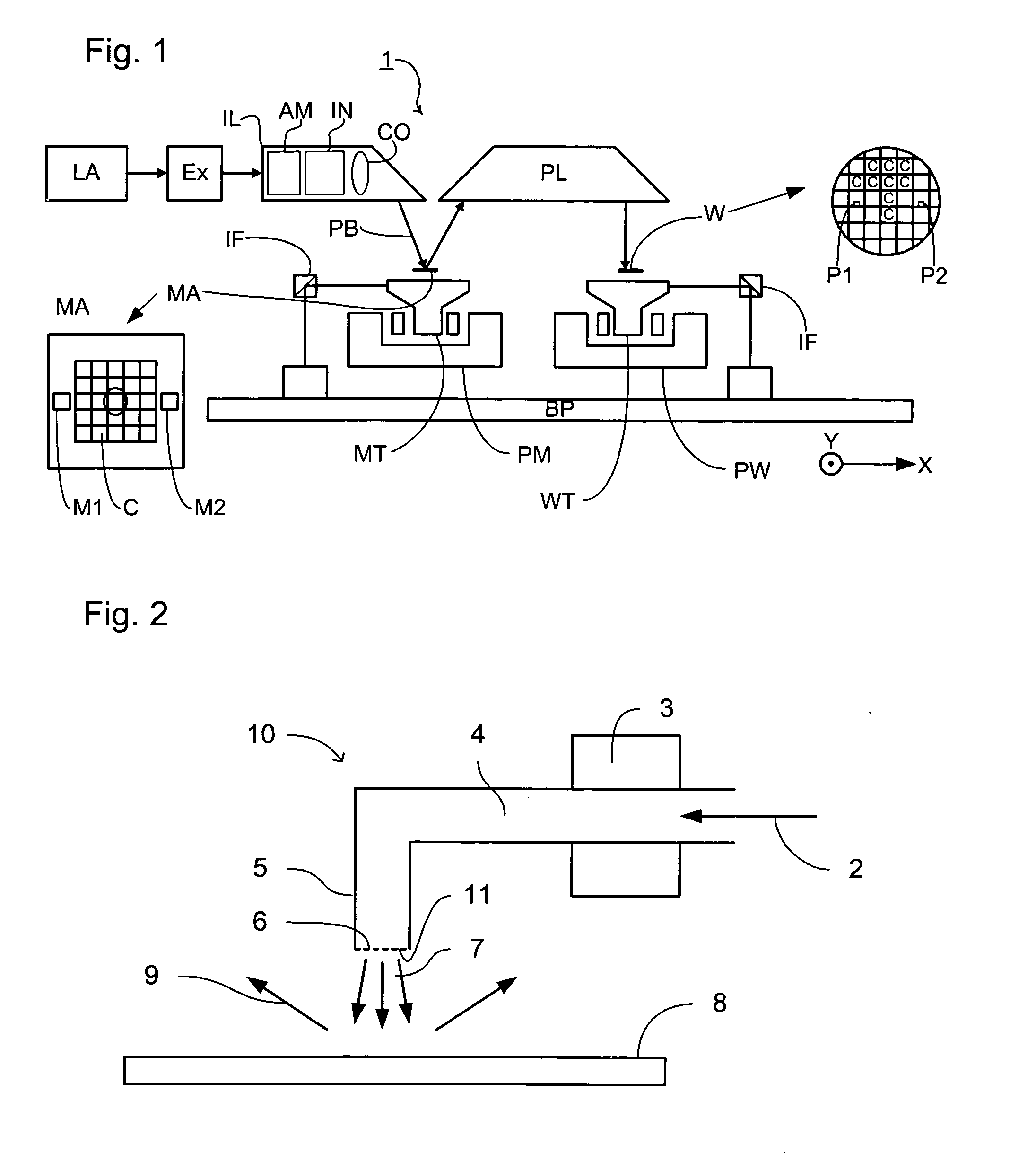
[0045] FIG. 1 schematically depicts a lithographic projection apparatus according to particular embodiments of the invention. The apparatus may comprise a radiation system Ex, IL, for supplying a projection beam PB of radiation (e.g. EUV radiation), which in this particular case also comprises a radiation source LA; a first object table (mask table) MT provided with a mask holder for holding a mask MA (e.g. a reticle), and connected to a first positioning device for accurately positioning the mask with respect to item PL; a second object table (substrate table) WT provided with a substrate holder for holding a substrate W (e.g. a resist coated silicon wafer), and connected to a second positioning device for accurately positioning the substrate with respect to item PL; and a projection system ("lens") PL (e.g. mirror group) for imaging an irradiated portion of the mask MA onto a target portion C (e.g. comprising one or more dies) of the substrate W. The term table ...


PUM


Abstract

A lithographic projection apparatus is disclosed. The apparatus includes a support structure constructed to support a patterning structure. The patterning structure is adapted to pattern a beam of radiation according to a desired pattern. The apparatus also includes a substrate holder that is constructed to hold a substrate, a projection system that is constructed and arranged to project the patterned beam onto a target portion of the substrate, and a downstream radical source that is connected to a gas supply and is configured to provide a beam of radicals onto a surface to be cleaned.

Description

[0001] This application is based on and claims priority from European Patent Application No. 02258605.1 filed on Dec. 13, 2002, the contents of which are incorporated herein by reference.[0002] 1. Field of the Invention[0003] The present invention relates generally to the field of lithography. More specifically, the present invention relates to cleaning surfaces in a lithographic projection apparatus.[0004] 2. Description of the Related Art[0005] The term "patterning device" or "patterning structure" as here employed should be broadly interpreted as referring to a device or structure that can be used to endow an incoming radiation beam with a patterned cross-section, corresponding to a pattern that is to be created in a target portion of the substrate; the term "light valve" can also be used in this context. Generally, the said pattern will correspond to a particular functional layer in a device being created in the target portion, such as an integrated circuit or other device (see ...

Claims


Application Information

Patent Timeline
IPC IPC(8): B08B7/00H01L21/027G03F7/20
CPCG03F7/70925B08B7/0057H01L21/027
Inventor VAN BEEK, MICHAEL CORNELISBAKKER, LEVINUS PIETERBISSCHOPS, THEODORUS HUBERTUS JOSEPHUSJONKERS, JEROENKROON, MARKWOLTERS, ROBERTUS ADRIANUS MARIAMAAS, ADRIANUS JOHANNES HENRICUS
Owner ASML NETHERLANDS BV
Why Eureka
Try Eureka