Manufacturing apparatus for carbon nanotube

a technology of carbon nanotubes and manufacturing apparatuses, which is applied in the manufacture of electric discharge tubes/lamps, energy-based chemical/physical/physico-chemical processes, plasma techniques, etc., and can solve problems such as difficult to obtain a few grams of sample, no particular boundary, and the controversy of carbon nanotube generating methods

Inactive Publication Date: 2004-09-02
FUJIFILM BUSINESS INNOVATION CORP
View PDF3 Cites 9 Cited by
  • Summary
  • Abstract
  • Description
  • Claims
  • Application Information

AI Technical Summary

Problems solved by technology

However, there is no particularly definite boundary therebetween.
However, a mechanism of generating carbon nanotubes with those methods is controversial in various respects, and a detailed growth mechanism is not disclosed even now.
However, with this method, it is extremely difficult to obtain a few grams of sample, so that the method is hardly used now.
However, the laser ablation supplies only a small quantity of carbon nanotubes, and the efficiency is low, leading to a high cost of a carbon nanotube.
In addition, the purity remains approximately 70 to 90%, and is not sufficiently high.
However, in the chemical vapor deposition, the growth rate of the carbon nanotube is extremely low, the efficiency is low, and industrial application is difficult.
In addition, a structure of the manufactured carbon nanotube has more defects and is incomplete compared with that synthesized in the arc discharge and the laser ablation.
However, in that case, the purity of the obtained carbon nanotube remains low.
Electrons, ions of carbon, radicals, and neutral particles in the arc plasma generated by the arc discharge repeat recollision, thereby generating complex chemical reactions, so that it is difficult to stably control the density and the kinetic energy of the carbon ions.
However, the physical characteristics and chemical characteristics of the carbon nanotubes, and those of the amorphous carbon particles and the graphite particles, which are major impurities, are approximately t...

Method used


Image

  • Manufacturing apparatus for carbon nanotube
  • Manufacturing apparatus for carbon nanotube
  • Manufacturing apparatus for carbon nanotube

Examples


example 1

[0134] The manufacturing apparatus shown in FIGS. 5 to 7 is used to manufacture a carbon nanotube. Hereinafter, description is made of specific requirements for the individual constitution of the manufacturing apparatus.

[0135] Reaction container 50: A cylindrical container chamber made of stainless steel. 182 mm in diameter and 89 mm in height. The thickness of the stainless steel is 9 mm.

[0136] Electrode (cathode) 11: A cylindrical graphite rod with an outer diameter of 5 mm (purity: 99.9% or more).

[0137] Electrode (anode) 12: A cylindrical graphite rod with an outer diameter of 15 mm (purity: 99.9% or more).

[0138] Tip position of the electrode 11: A position displaced by 42 mm toward the electrode 12 side from a center of each of the permanent magnets 20 to 23 in an axial direction of the electrode 11 and the electrode 12.

[0139] Moving apparatus 13: Capable of moving the electrode 11 with a stepping motor. Adjusts to maintain the interval between the electrodes 11 and 12 constant ...

example 2

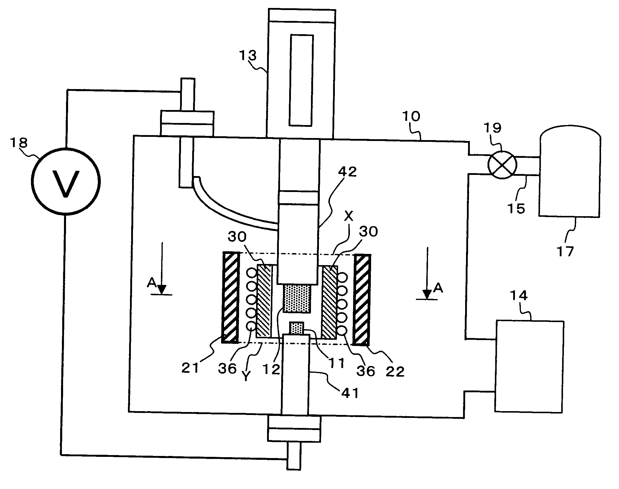
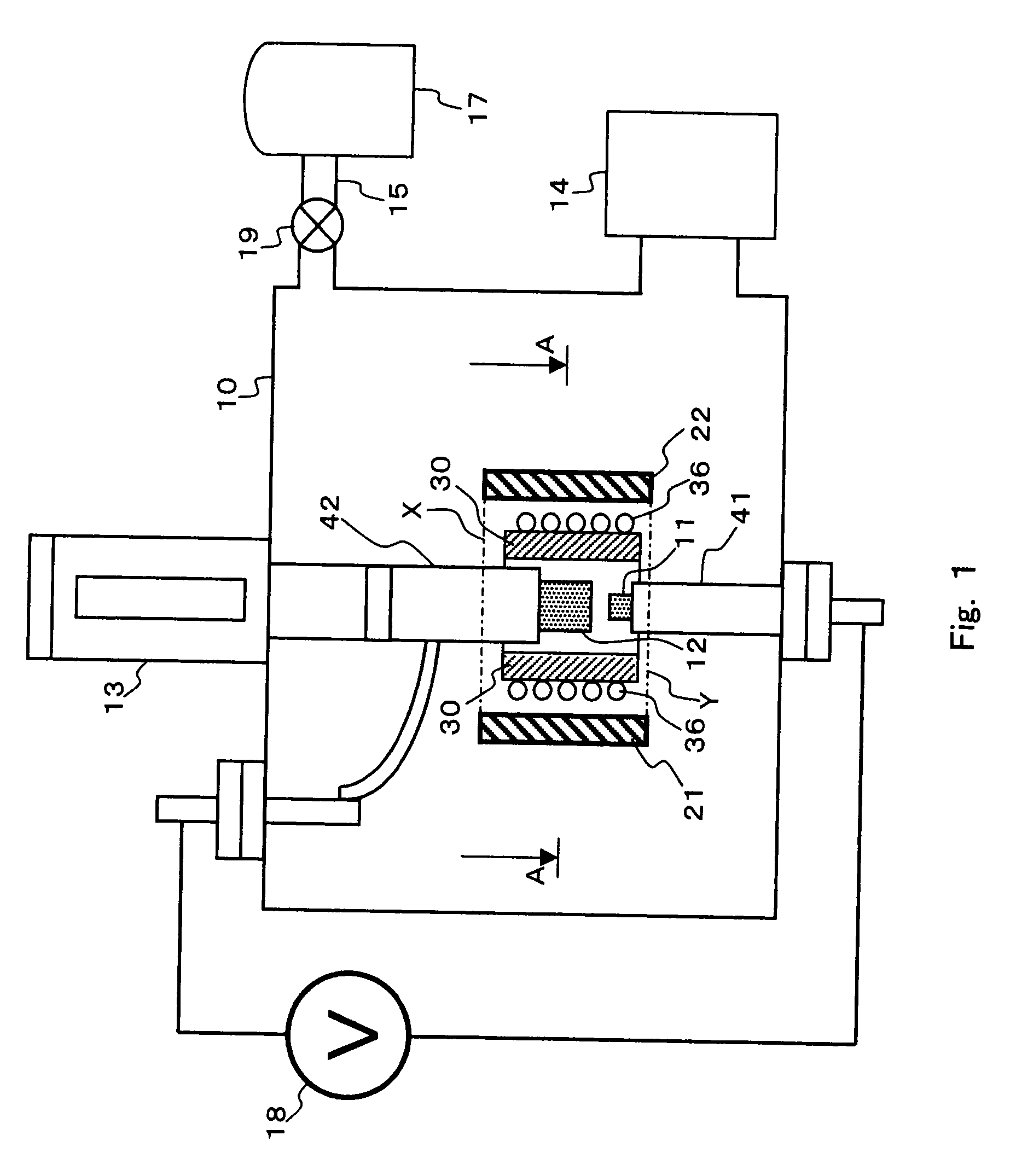
[0147] The manufacturing apparatus shown in FIG. 1 (and FIG. 2) is used to manufacture a carbon nanotube. Specific requirements for the individual constitution of the manufacturing apparatus are as follows.

[0148] Reaction container 10: A cylindrical container chamber made of stainless steel. 210 mm in diameter and 380 mm in length.

[0149] Electrode (cathode) 11: A cylindrical graphite rod with an outer diameter of 5 mm (purity: 99.9% or more).

[0150] Electrode (anode) 12: A cylindrical graphite rod with an outer diameter of 15 mm (purity: 99.9% or more).

[0151] Moving apparatus 13: Capable of moving the electrode 11 with a stepping motor. Adjusts to maintain the interval between the electrodes 11 and 12 constant during plasma discharge.

[0152] Power supply 18: A DC arc welding power supply (Osaka Denki AR-SB300) capable of controlling the current from 20 A to 300 A.

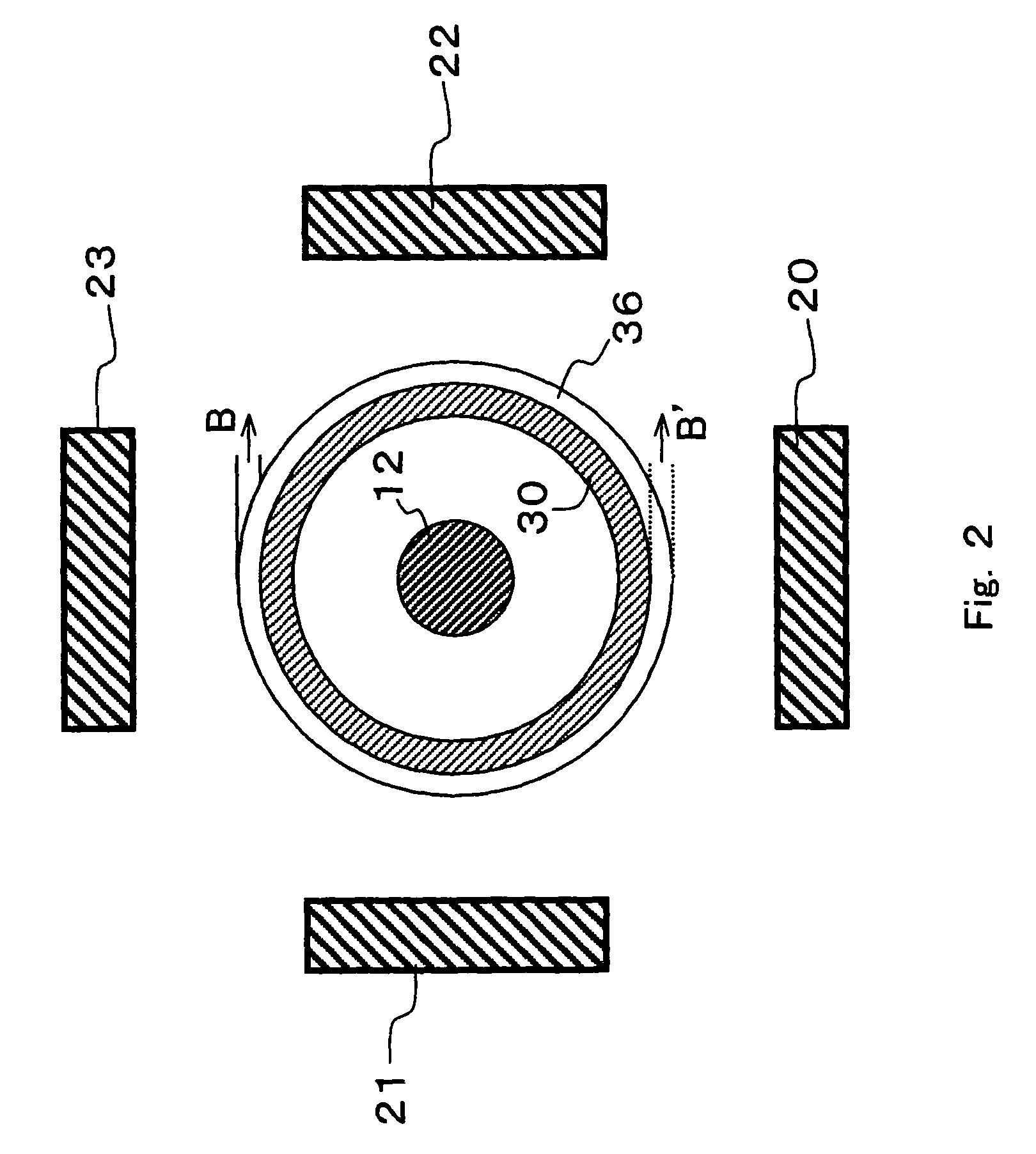
[0153] Permanent magnets 20 to 23: Cylindrical NdFB permanent magnets with a diameter of 22 mm and a thickness of 10 mm (Ni...


PUM


Abstract

Provided is a manufacturing apparatus for a carbon nanotube including: at least two electrodes whose tips are opposed to each other; at least a power supply that applies a voltage between the two electrodes to generate discharge plasma in a discharge area between the two electrodes; and at least a plurality of magnets that generates, in a generation area of the discharge plasma, at least one of a magnetic field of multiple directions and a magnetic field having a component in parallel with a flowing direction of a discharge current, in which a thermal shield wall made of a non-magnetic material is disposed between the magnets and the generation area of the discharge plasma. Accordingly, an influence on the magnetic field due to the heat generated from the discharge plasma can be suppressed, and a high-purity carbon nanotube with excellent industrial efficiency can be stably manufactured.

Description

FIELD OF THE INVENTION AND RELATED ART STATEMENT[0001] The present invention relates to a manufacturing apparatus for a carbon nanotube whose industrial availability has been attracting attention in recent years.[0002] A material having a diameter of 1 .mu.m or smaller which is finer than a carbon fiber is generally called a carbon nanotube and distinguished from the carbon fiber. However, there is no particularly definite boundary therebetween. By a narrow definition, the material whose hexagonal mesh carbon surface is substantially parallel to an axis is called a carbon nanotube, and even a variant of the carbon nanotube, around which amorphous carbon exists, is included in the carbon nanotube (note that the narrow definition is applied to the carbon nanotube according to the present invention).[0003] In general, the narrowly-defined carbon nanotube is further classified into two types: a carbon nanotube having a structure with a single hexagon mesh tube (graphene sheet) is called...

Claims


Application Information

Patent Timeline
IPC IPC(8): B01J19/08C01B31/02H01J37/32H05H1/24H05H1/50
CPCB01J19/088Y10S977/844B01J2219/0822B01J2219/083B01J2219/0839B01J2219/0852B01J2219/0866B01J2219/0871B01J2219/0879B01J2219/0898B82Y30/00B82Y40/00C01B31/0226H01J37/32055H01J37/32623H01J37/3266H01J2209/0223H05H1/24H05H1/50B01J2219/0809C01B32/16
Inventor HIRAKATA, MASAKIKISHI, KENTAROANAZAWA, KAZUNORIWATANABE, HIROYUKISHIMIZU, MASAAKI
Owner FUJIFILM BUSINESS INNOVATION CORP
Why Eureka
Try Eureka