
UV/EB cured integrated magnets-composition and method of fabrication

a technology of integrated magnets and composite materials, applied in the direction of magnetic materials, magnetic recording, coating carrier supports, etc., can solve the problems of inability to meet the immediate design needs of customers, the size and shape of design artworks, and the waste of upstream processing, so as to reduce costs and prolong the life of dies

Inactive Publication Date: 2004-09-30
SOVEREIGN SPECIALTY CHEM
View PDF19 Cites 11 Cited by
  • Summary
  • Abstract
  • Description
  • Claims
  • Application Information

AI Technical Summary

Benefits of technology

"The patent describes a new method for creating magnetic pieces that can be used for advertising and personalization purposes. The method involves using a radiation curable magnetic composition that can be applied directly to a non-magnetic substrate and then cured. The resulting magnetic pieces are much thinner and lighter than traditional magnets, reducing shipping costs. The method also allows for the pattern application of the magnetic composition, reducing waste and shipping costs. The magnetic pieces can be used for adhesion to iron-based surfaces and can be produced on a wide range of substrates. Overall, the patent provides a more efficient and cost-effective way to create magnetic pieces for various applications."

Problems solved by technology

However, the described processes do not address the on-demand shape and size needs, the upstream processing waste, the multiple steps required for the pre-processed magnetic pieces, or the die cutting problems associated with the production, processing, and finishing of traditional magnets.
Specifically, the above-mentioned prior art processes for processing and finishing refrigerator and office magnets have a number of drawbacks.
There are also multiple bottlenecks for production speed and efficiency.
Specifically, the above-mentioned processes restrict the sizes and shapes of the design artwork and cannot accommodate the immediate design needs of the customer.
Moreover, the above-described processes limit the flexibility, quantity, and capability of mass production of magnets that also carry personalized information or advertising since the traditional vinyl magnet substrate is not a good receptor of imaging inks used in personalization as well as the inherent thermal instability of the vinyl substrate itself (this being a problem due to high heat associated with personalized imaging).
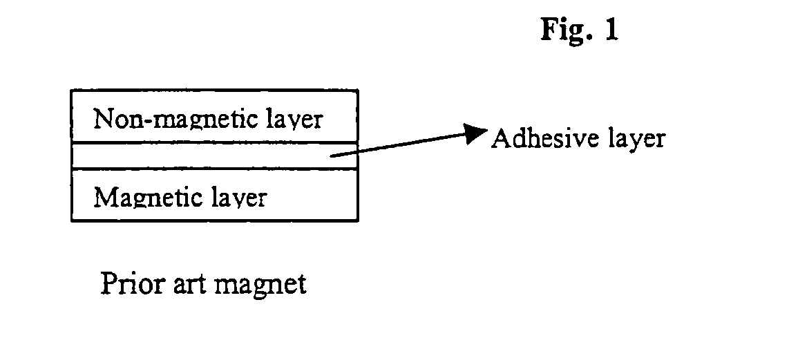
Because the ferrite magnet is overlaid to the entire surface of the substrate, the above-described prior art methods create a lot of trimming and die-cutting waste, particularly magnetic waste.
Likewise, because the dies have to cut through the traditional magnet layer (typically 8-15 mils / 200-375.mu. thick), which is almost always harder than the substrate layer(s), the dies have a short life and require frequent replacement.
Even though Bell utilized printable and curable magnetic compositions to create predetermined pattern using a screen printing process, the compositions disclosed in Bell presents several problems for a in-line process.
Further, the method disclosed in Bell, can only deal with sheet-fed type operation due to the curing schedule and the subsequent laminating process.
Finally, the curable composition in Bell is designed for motor type application is too hard and not flexible enough for a typical in-line printing equipment where the cured web / sheet with magnets has to wrap around and move along over sets of moving rollers to be processed.

Method used


Image

  • UV/EB cured integrated magnets-composition and method of fabrication
  • UV/EB cured integrated magnets-composition and method of fabrication
  • UV/EB cured integrated magnets-composition and method of fabrication

Examples


example 1

Preparation of an Integrated Magnet (A Composite Object) of the Present Invention Using a Radiation Curable Magnetic Coating Composition

[0094]

4 1,6-hexanediol diacrylate (HDDA) 6.91 wt % PHOTOMER 5429 (polyester acrylate oligomer) 0.97 wt % Amine acrylate monomer 1.45 wt % (adducts of HDDA & diethanolamine) ITX (2-isopropylthioxanthone) 0.10 wt % IRGACURE 907 (from Ciba-Geigy) 0.05 wt % (2-methyl-1-[4-(methylthio)phenyl]-2-morphol-inopropan-1-one) TPO-L (initiator) (Phosphine oxide type from BASF) 0.74 wt % CN966J75 (SartomerCo.) (polyurethane acrylate 1.38 wt % oligomer) MQP-S-9-8 (Magnequench Int., Inc.) 88.40 wt % (isotropic, spherical NdFeB magnetic powder) Total 100.00%

[0095] The binder portion, consisting of the above listed components with the exception of the magnetic particles, was made first by combining the components with mixing. Then, the rare-earth magnetic material, MQP-S-9-8, was mixed in just before use. The resulting radiation curable magnetic composition was appli...

example 2

Preparation of an Integrated Magnet (A Composite Object) of the Present Invention Using a Radiation Curable Magnetic Coating Composition

[0101] A radiation curable magnetic composition comprising the following components was prepared according to the process described in Example 1:

5 1,6-hexanediol diacrylate (HDDA) 6.91 wt % PHOTOMER 5429 0.97 wt % Amine acrylate 1.45 wt % (adducts of HDDA & diethanolamine) ITX (2-isopropylthioxanthone) 0.10 wt % IRGACURE 907 0.05 wt % TPO-L (BASF) 0.74 wt % CN966J75 (SartomerCo.) 1.38 wt % MQP-S-11-9 (Magnequench Int., Inc) (isotropic, 88.40 wt % spherical, NdFeB magnetic powder with slightly higher energy output than S-9-8) Total 100.00%

[0102] The resulting radiation curable magnetic composition was then applied on 10 lb C1S paper stock with a wire wound rod #30 to approximately 3 mils thick and cure with both AETEK's unit and Fusion unit and similar cure energy as mentioned in Example 1. The prepared paper magnet samples are then magnetized with t...

example 3

Preparation of an Integrated Magnet (A Composite Object) of the Present Invention Using a Radiation Curable Magnetic Coating Composition

[0103] A radiation curable magnetic composition comprising the following components was prepared according to the process described in Example 1:

6 1,6-hexanediol diacrylate (HDDA) 6.91 wt % PHOTOMER 5429 0.97 wt % Amine acrylate 1.45 wt % (adducts of HDDA & diethanolamine) CN966J75 (SartomerCo.) 1.77 wt % Paint additive #57 (Dow Corning) 0.50 wt % MQP-S-9-8 (Magnequench Int., Inc) 88.40 wt % Total 100.00%

[0104] The resulting radiation curable magnetic composition was then applied on 10 lb C1S paper stock with a wire wound rod #30 to approximately 3 mils thick and cure with a lab EB unit from Energy Sciences Inc. (Wilmington, Mass.) with curing dosage of 165 KV and 3 Mrad. The prepared paper magnet samples are then magnetized with the same magnetizer used for Example 1. The samples were adequate for the intended application.


PUM

PropertyMeasurementUnit
weight %aaaaaaaaaa
thicknessaaaaaaaaaa
thickaaaaaaaaaa

Abstract

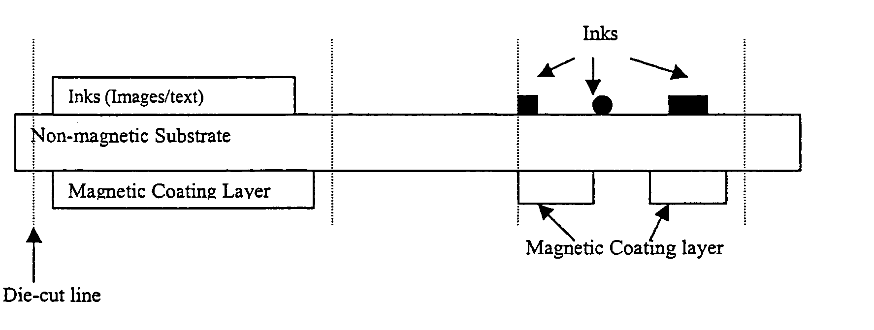
The present invention comprises a radiation curable composition for in-line printing containing magnetic pigments capable of being magnetized to possess permanent magnetic properties after the composition is cured. The composition is cured by an ionizing radiation source, preferably by UV light or electron beam radiation (UV / EB). The present invention is also directed to an in-line process for printing magnetic images on non-magnetic substrate, comprising: pattern applying the above mentioned radiation curable composition on the substrate opposite to a print side, pre-aligning the magnetic pigment particles (if necessary) of the applied composition, curing the composition by ionizing radiation source (UV / EB), magnetizing the cured composition, then finishing the final piece. The finishing step could involve delivering the final piece in a simple sheet with die cut magnets or creating an "integrated magnet" format involving plow folding over the magnet panel, pattern coating or flood coating an adhesive that will only adhere the non-magnet matrix areas between die cut magnets, thus, allowing for the individual magnets to be "popped" out of the carrier by the final end user. The resulting magnetized pieces will possess holding power like magnets (refrigerator and office magnets) and are capable of carrying personalized, Scitex imaged and direct marketing information (including redemption value for coupons, local public service access numbers, etc.)

Description

I. BACKGROUND[0001] A. Field of the Invention[0002] The present invention has multiple aspects. In its simplest aspect, it is directed to a radiation curable composition for in-line printing and containing magnetic particles capable of being magnetized to possess permanent magnetic properties when the composition is cured. In its second aspect, the present invention is directed to an in-line process for printing magnetic images on non-magnetic substrate, comprising: pattern applying the above mentioned radiation curable composition on the substrate, typically opposite to a print side, pre-aligning the magnetic pigment particles (if necessary) of the applied composition, curing the composition by ionizing radiation source (UV / EB), magnetizing the cured composition, and then finishing the final piece. In its third aspect, the present invention is directed to a non-magnetic substrate having a radiation cured magnetic coating adhering to at least one side.[0003] B. Background of the Inv...

Claims


Application Information

Patent Timeline
Patent Type & Authority Applications(United States)
IPC IPC(8): B41M7/00C08K3/08C09D11/10G11B5/855H01F1/00H01F1/08H01F41/16
CPCC08K3/08C09D11/101G11B5/855Y10T428/32H01F1/083H01F41/16B41M7/0081H01F1/0027
Inventor GAO, XINHAOGOLDSTEIN, SCOTT D.LIN, ANSHYANG ALBERTJOHNSTON, RICHARD WILLIAM
Owner SOVEREIGN SPECIALTY CHEM
Learn More