Solid fuel burner, burning method using the same, combustion apparatus and method of operating the combustion apparatus

a solid fuel burner and burner technology, applied in the direction of combustion types, lighting and heating apparatus, domestic stoves or ranges, etc., can solve the problems of low melting temperature of combustion ash, low calorific value of fuels, and low grindability or pulverization properties of fuels

Inactive Publication Date: 2004-10-28
HITACHI LTD +1
View PDF9 Cites 32 Cited by
  • Summary
  • Abstract
  • Description
  • Claims
  • Application Information

AI Technical Summary

Problems solved by technology

Furthermore, these fuels are low in calorific value compared to coal of a high coalification rank such as bituminous coal and anthracite, and are generally low in grindability or pulverizability.
In addition, these fuels have a property of low melting temperature of combustion ash.
Since these solid fuels contain much volatile matters, these solid fuels easily self-ignite in a storage process, a pulverizing process and a transportation process under air atmosphere, and accordingly are difficult to be handled compared to bituminous coal.
However, when the fuel is ejected from a solid fuel burner, the oxidation reaction of the fuel transported by the transporting gas of a low oxygen concentration is limited by the oxygen concentration around the fuel.
Therefore, the combustion speed is slow compared to that in a case of fuel transported by air.
Further, the flame temperature is low because the combustion speed is slow.
As the result, the reduction reaction of nitrogen oxides NOx to nitrogen activated in a Nox reducing zone of high temperature (about 1000 C..degree. or higher) is difficult to be used, and accordingly the concentration of NOx at the exit of the furnace becomes higher compared to the case of transporting the fuel using air.
However, when the air ejected from the additional air nozzle is ejected in parallel to the direction of the fuel jet, the mixing between the fuel jet and the additional air becomes slow because the speed differe

Method used


Image

  • Solid fuel burner, burning method using the same, combustion apparatus and method of operating the combustion apparatus
  • Solid fuel burner, burning method using the same, combustion apparatus and method of operating the combustion apparatus
  • Solid fuel burner, burning method using the same, combustion apparatus and method of operating the combustion apparatus

Examples


embodiment 1

[0100] Embodiment 1

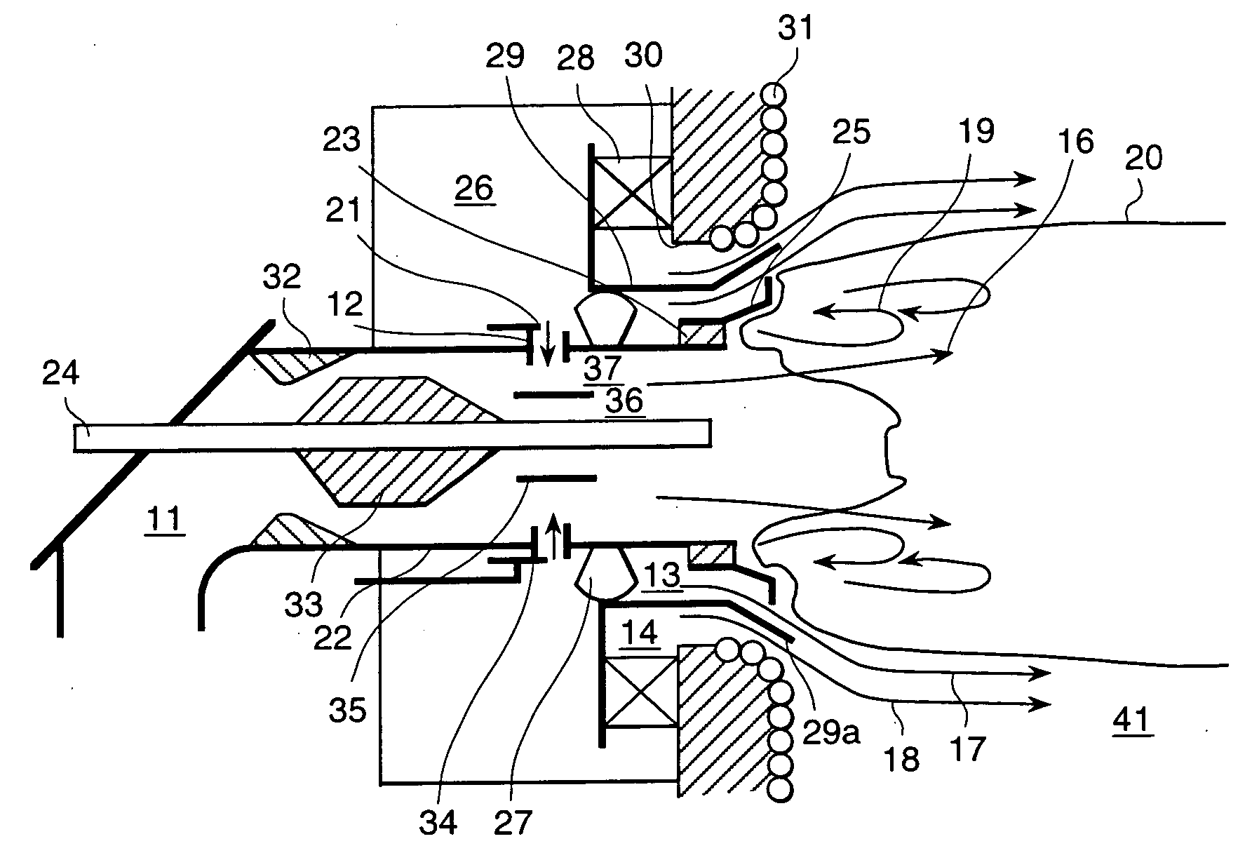
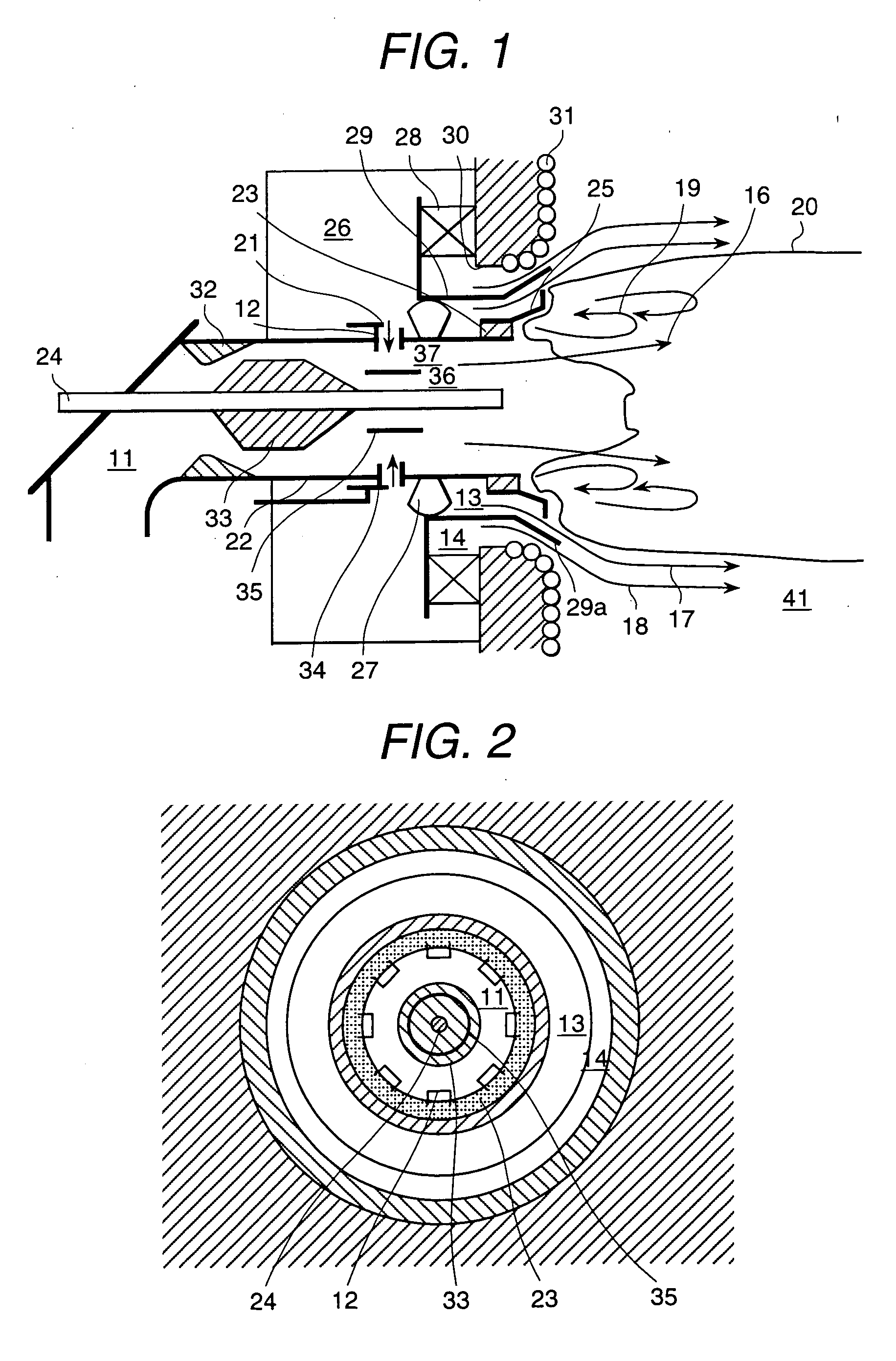
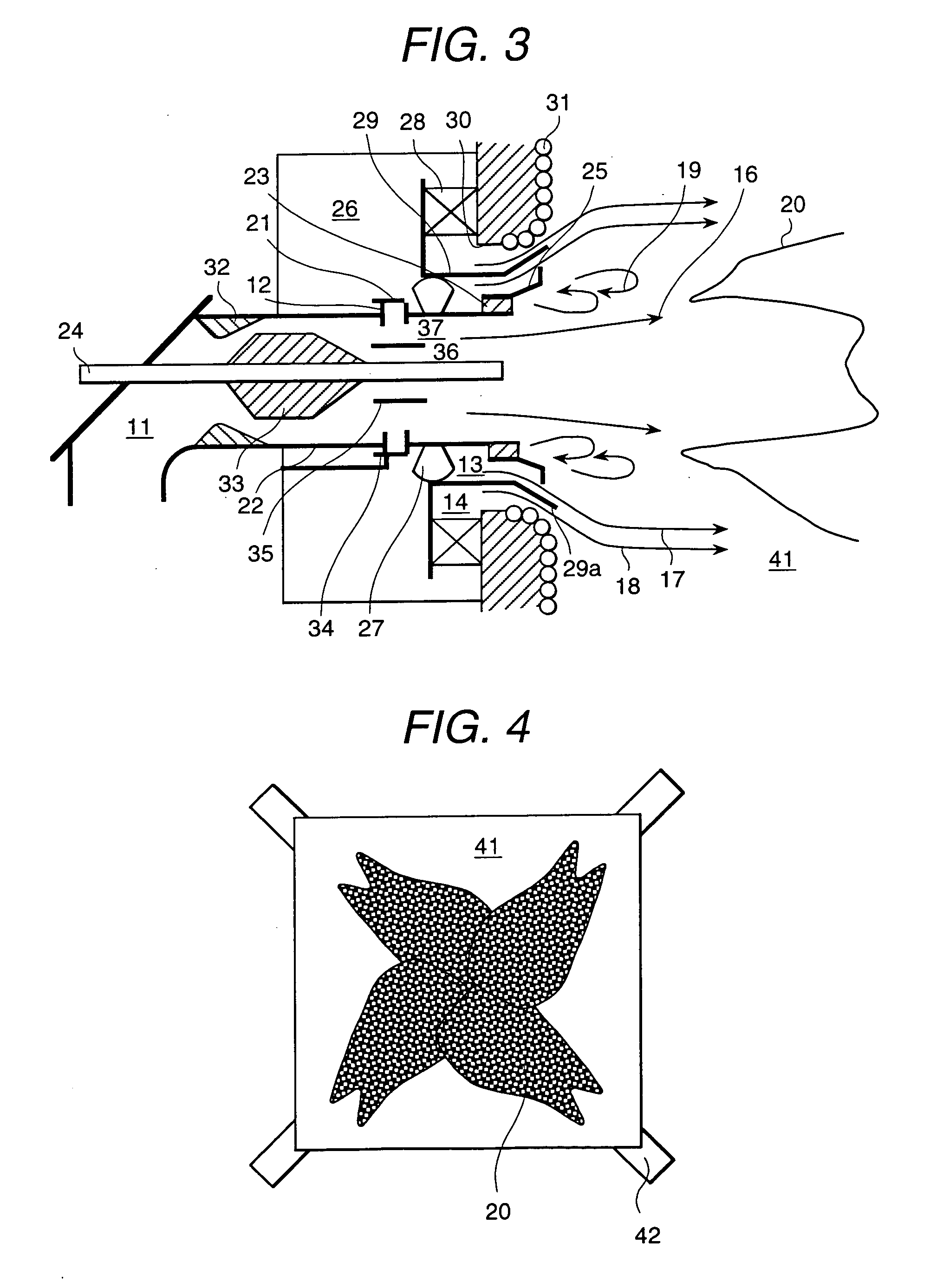
[0101] FIG. 1 is a cross-sectional view showing the structure of an embodiment 1 of the solid fuel burner in accordance with the present invention, and the view shows a state in which the flame 20 of the solid fuel burner is formed near a circulation flow 19 in the downstream side of a flame stabilizing ring 23 when the embodiment 1 of the solid fuel burner is used under a low load condition. FIG. 2 is a schematic view showing the structure of the embodiment 1 of the solid fuel burner, viewed from the inner side of the furnace 41.

[0102] The solid fuel burner of the present embodiment 1 comprises a combustion improving oil gun 24 in the central portion; and a fuel nozzle 11 for ejecting the mixed fluid of the fuel and the transporting gas of the fuel around the combustion improving gun 24. A plurality of additional air nozzles 12 are arranged so that the nozzle exits are directed from an outer side separation wall 22 of the fuel nozzle 11 toward the center axis of ...

embodiment 2

[0146] Embodiment 2

[0147] FIG. 8 is a cross-sectional view showing the structure of an embodiment 2 of a solid fuel burner without any concentrator in accordance with the present invention, and the view shows a state in which fuel ejected from the solid fuel burner under a low load condition is burning. In the embodiment 1, the concentrator 33 is arranged in the fuel nozzle 11. However, even without the concentrator 33 as the present embodiment 2, when air is ejected from the additional air nozzle in the direction nearly perpendicular to the direction of the fuel jet flowing inside the fuel nozzle 11, the speed difference between the fuel particles and the air becomes larger than in the case of ejecting the additional air in parallel to the direction of the fuel jet, and the fuel jet and the air are mixed with each other similarly to the case of the embodiment 1.

[0148] Further, the additional air nozzle 12 and the separator 35 are arranged at the position overlapping in a direction ...

embodiment 3

[0151] Embodiment 3

[0152] FIG. 9 is a cross-sectional view showing the structure of an embodiment 3 of a solid fuel burner in accordance with the present invention, and the view shows a state in which fuel ejected from the solid fuel burner under a low load condition is burning. Main different points of the present embodiment 3 from the embodiment 1 are that the fuel nozzle 11 is rectangular and that the air nozzle 13 is arranged beside the fuel nozzle 11.

[0153] The inside of the fuel nozzle 11 is constructed of an obstacle (concentrator) 33 and a separator 35 arranged in this order from the upstream side, and the obstacle 33 is set at a position on a separation wall opposite to the air nozzle 13 of the fuel nozzle 11. The additional air nozzle 12 is set in a direction that the air ejected toward the outer side separation wall 22 of the fuel nozzle 11 becomes nearly perpendicular to the flow direction of the mixed fluid flowing through the fuel nozzle 11. At that time, the exit of t...


PUM


Abstract

A solid fuel burner using a low oxygen concentration gas as a transporting gas of a low grade solid fuel such as brown coal or the like and a combustion method using the solid fuel burner are provided. The solid fuel burner comprises a means for accelerating ignition of the fuel and a means for preventing slugging caused by combustion ash from occurring. Mixing of fuel and air inside a fuel nozzle 11 is accelerated by that an additional air nozzle 12 and a separator 35 for separating a flow passage are arranged in the fuel nozzle 11, and the exit of the additional air nozzle 12 is set at a position so as to overlap with the separator 35 when seeing from a direction perpendicular to a burner axis, and additional air is ejected in a direction nearly perpendicular to a flow direction of a fuel jet flowing through the fuel nozzle 11. An amount of air from the additional air nozzle 12 is varied corresponding to a combustion load. By increasing the amount of air from the additional air nozzle 12 at a low load operation, an oxygen concentration of a circulation flow 19 formed in a downstream portion outside the exit of the fuel nozzle 11 is increased to stably burn the fuel. By decreasing the amount of air from the additional air nozzle 12 at a high load operation, a flame is formed at a position distant from the fuel nozzle 11 to suppress radiant heat received by structures of the solid fuel burner and walls of the furnace.

Description

[0001] 1. Field of the Invention[0002] The present invention relates to a solid fuel burner for burning solid fuel by transporting the solid fuel using gas-flow, and particularly to a solid fuel burner suitable for pulverizing, transporting using gas-flow and then suspension-burning a fuel containing much moisture and volatile matters such as wood, peat, coal or the like, and a burning method using the solid fuel burner, a combustion apparatus comprising the solid fuel burner and a method of operating the combustion apparatus.[0003] 2. Description of Prior Art[0004] Wood, peat and coal of a low coalification rank such as blown coal and lignite which are typical thereof contain much moisture. Further, classifying fuel components into volatile matters of a component released as gas when heated, char (fixed carbon) of a component remaining as solid, ash of a component remaining as incombustible matters and moisture, these fuels contain much moisture and volatile matters and a little ch...

Claims


Application Information

Patent Timeline
IPC IPC(8): F23D1/00F24B1/187
CPCF23C6/045F23C7/004F23C7/008F23C2201/20F23C2900/06041F23D1/00F23D2201/10F23D2201/20F23D2209/20F24B1/187
Inventor OKAZAKI, HIROFUMITANAIGUCHI, MASAYUKITSUMURA, TOSHIKAZUTAKAHASHI, YOSHITAKAKURAMASHI, KOUJI
Owner HITACHI LTD
Why Eureka
Try Eureka