Device and method for converting an optical frequency

a technology of optical frequency and conversion method, applied in the field of optical frequency conversion device and method, can solve the problems of optical loss increase, inability to complete spatial walk-off compensation, and high cost in practi

Inactive Publication Date: 2004-12-02
LUMERA LASER
View PDF9 Cites 19 Cited by
  • Summary
  • Abstract
  • Description
  • Claims
  • Application Information

AI Technical Summary

Problems solved by technology

This is a requirement which in practice can only be achieved at very high cost, since the necessary precision of the angle adjustment in critically phase-adapted frequency conversion processes is typically less than 0.1 degree and also in the optimum configuration two crystals must be set with this precision.
Furthermore in this state of the art compensation for the spatial walk-off is not complete.
Also in such an arrangement the optical losses increase even if anti-reflection coatings are applied to the crystal facets.
The disadvantage is furthermore that the newly generated beam must run through all surfaces.
In particular for the production of ultra-violet (UV) light at high power, problems can arise in respect of interference and hence the life of the surfaces of the non-linear crystals.
A further serious disadvantage of arrangements of 2.sup.n frequency conversion crystals (n.gtoreq.1) is the increased cost.
This method however has disadvantages.
It is shown however that this condition cannot always be fulfilled.
A further disadvantage is that for frequency doubling with this method, compensation for walk-off is possible only in crystals with type II phase adaptation.
The disadvantage is also that due to the non-perpendicular irradiation, the beams in the non-linear crystal undergo a change in beam cross section.
For this known methods are available such as the use of cylinder optics or spherical resonator mirrors with non-perpendicular incidence, which however all entail an increased cost.
There is no compensation for run time differences and the method given i.e. the non-perpendicular irradiation into the crystal, cannot achieve this.
The disadvantage i

Method used


Image

  • Device and method for converting an optical frequency
  • Device and method for converting an optical frequency
  • Device and method for converting an optical frequency

Examples


Embodiment Construction

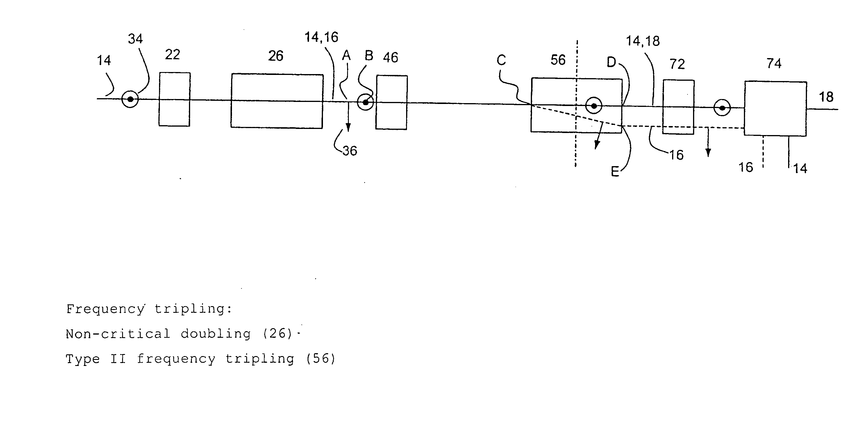
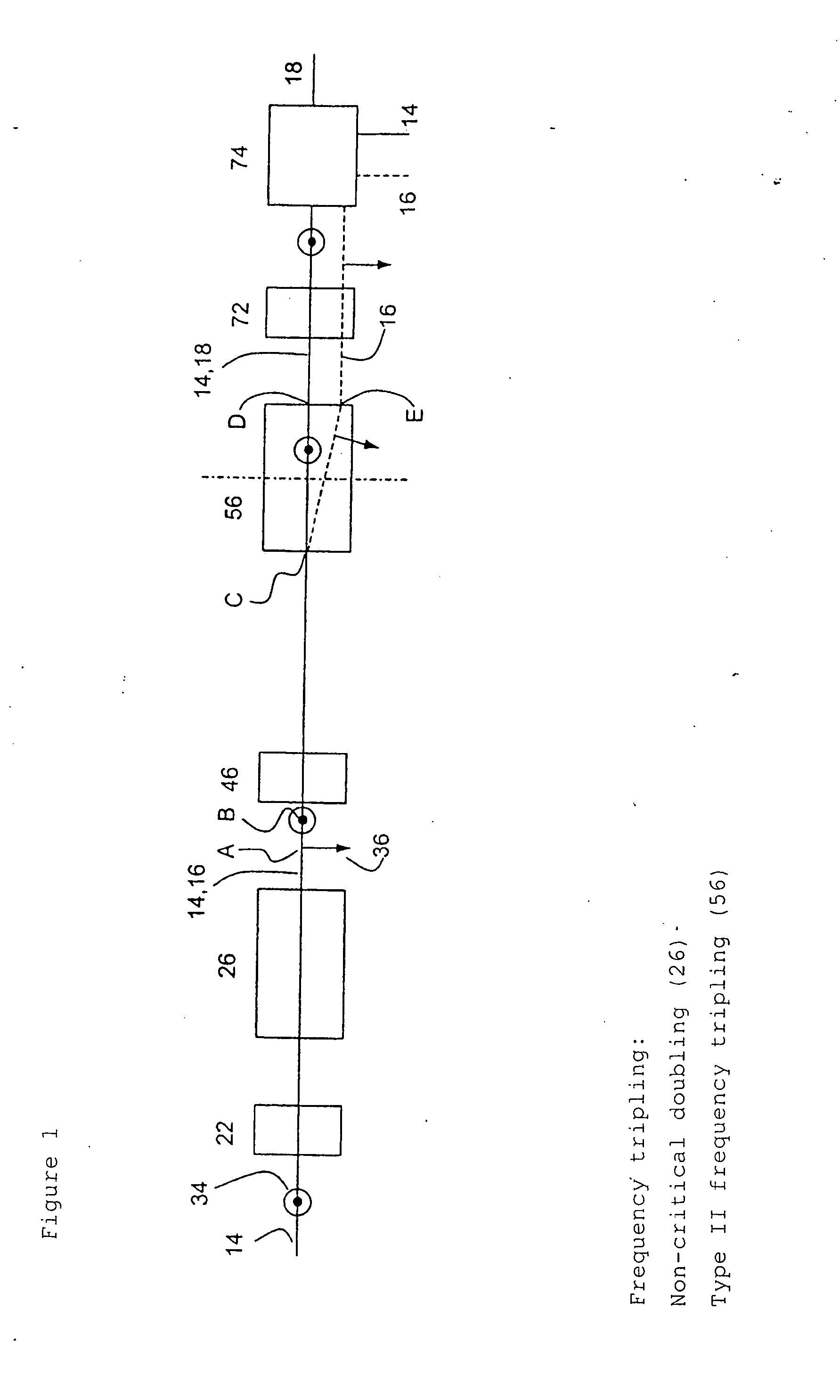
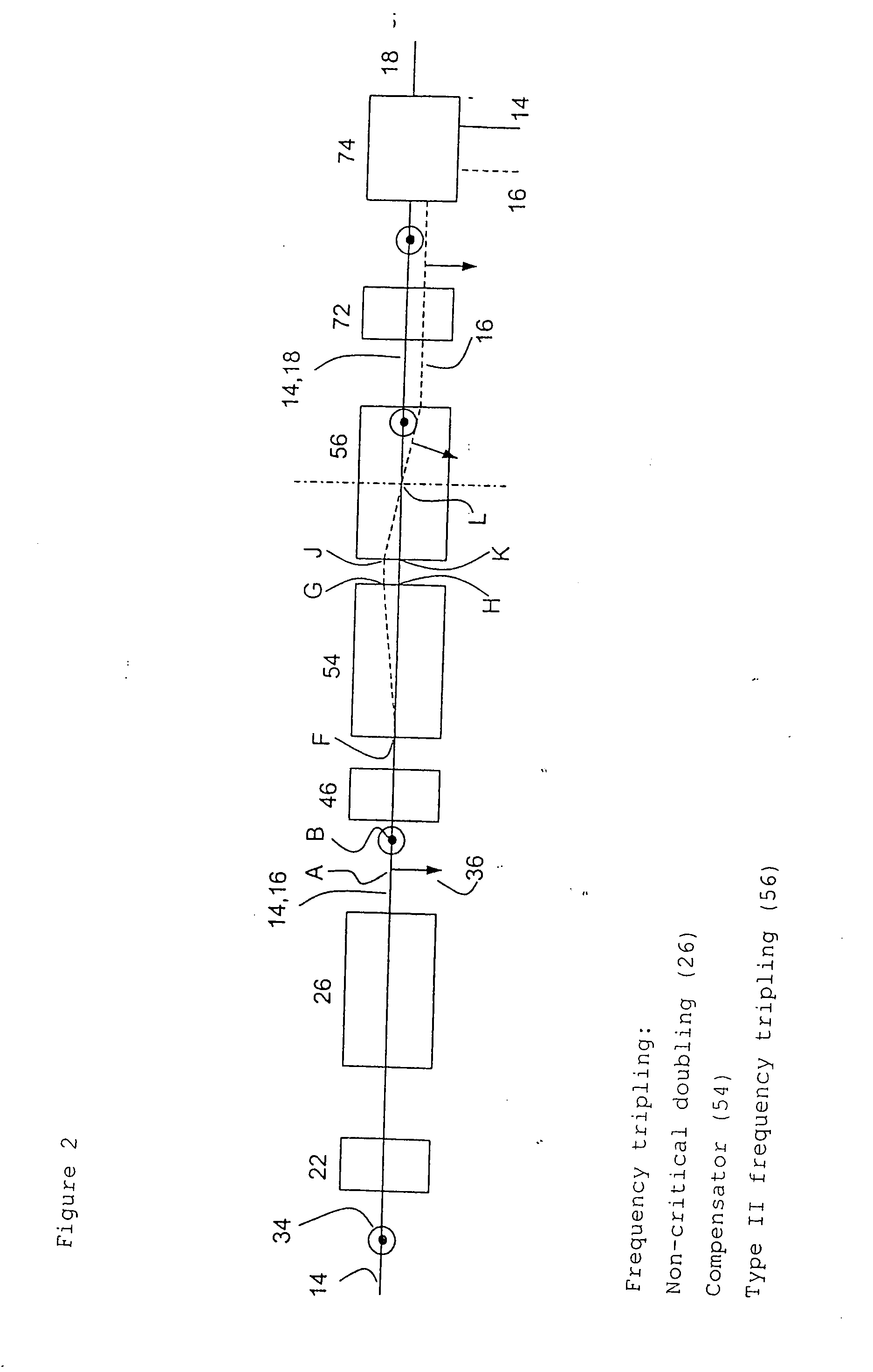
Frequency Tripling of a Mode-Coupled Nd:YVO.sub.4 Laser

[0064] To generate the third harmonic of a mode-coupled ND:YVO.sub.4 laser with a fundamental wavelength of 1064 nm, the frequency-doubled radiation with a wavelength of 532 nm is generated in lithium triborate (LBO). The frequency doubling is of type I, i.e. the polarisation of the generated second harmonic is perpendicular to the polarisation of the fundamental wave. The LBO crystal has a x-cut, i.e. the y and z main axes of the crystal are oriented perpendicular to the beam direction. The LBO is operated at a temperature of around 150.degree. C., where the frequency doubling is non-critical without a spatial walk-off between the fundamental wave and the frequency-doubled wave. The two beams run collinear in the LBO crystal and after emerging from the LBO crystal. The group speeds of the 1064 nm pulse and the 532 nm pulse are different in the LBO crystal because of dispersion. This gives a temporal offset between two pulses wh...


PUM


Abstract

To optimise the transformation rate (efficiency) in the optical frequency conversion of laser beams of ultra-short light pulses in optically non-linear media such as a crystal (56), a double refracting crystal (54) is arranged in the beam path before the optically non-linear medium (56). The length of the double refracting crystal (54) is selected and the orientation of its optical crystal axis in relation to the propagation direction of the laser beams involved in the frequency conversion is set such that the change caused by the double refracting crystal (54) in the location, time and direction of incidence of the laser pulses (14) and (16) on the optically non-linear medium (56) and the resulting change in the spatial and temporal overlap of the laser pulses in the optically non-linear medium (56) for optical frequency conversion in the crystal (56) give a conversion efficiency which is higher than the conversion efficiency which would be achieved without the double refracting crystal (54).

Description

[0001] The invention concerns a device for optical frequency conversion according to the preamble of claim 1, a method for optical frequency conversion according to the preamble of claim 10, and the use of a double refracting crystal to optimise an optical frequency conversion in at least one optically non-linear medium.[0002] The optically non-linear frequency conversion of laser beams is a known process for generating from laser light of frequency .omega., laser light with a different frequency. Examples of optically non-linear frequency conversion are three-wave mixed processes such as sum frequency mixing (SFM), frequency doubling (SHG), difference frequency generation (DFG) and optically parametric oscillation (OPO). The medium in which the frequency conversion takes place is usually an optically non-linear crystal. One important parameter in all optically non-linear processes is the transformation rate (efficiency). The transformation rate indicates how much of the beam power ...

Claims


Application Information

Patent Timeline
IPC IPC(8): G02F1/35
CPCG02F1/3534G02F2001/354G02F2001/3507G02F1/3507G02F1/354
Inventor NEBEL, ACHIMHENRICH, BERNHARDHERRMANN, THOMAS
Owner LUMERA LASER
Why Eureka
Try Eureka