Conventional battery technologies based on lead acid,
nickel-
cadmium, or
nickel-metal hydrides have limited
operation time, long recharge time, low
energy density, hazardous chemical materials requiring special encapsulation containers and careful disposal, fixed
electrode areas, and in electrical automobile applications, conventional battery systems result in limited driving distances.
However, they deliver less power, have a faster self-
discharge rate, and are less tolerant of overcharging.
However, a major drawback with this
battery cell design is that
lithium's high reactivity with liquid electrolytes erodes the electrodes of such battery cells.
While recent developments in
solid state electrolytes have reduced this problem, a number of problems still remain, namely:
dendrite formation on the electrodes; and the hazardous effects of
lithium on the environmental.
Zinc-air battery technology is environmental friendly, but current batteries are limited to fixed area, resulting in low perceived specific
power rating.
However, batteries with all of these desirable characteristics do not yet exist.
Traditional battery designers continue to adopt the fixed area design methodology and, therefore, are hindered by fundamental constraints including: (1) the larger the
battery capacity, the longer it takes to recharge; (2) every unit weight of the
anode is nearly matched by the weight of the
cathode, the weight of the
electrolyte, as well as the weight of the container; this overhead is the source of low
energy density; (3) pulse power is inversely related to the energy capacity; and (4) only one set of electrodes are available for the sequential
discharge and recharge cycles.
There are basic manufacturing challenges, as yet unsolved, in
mass producing these cells.
), because of the limitations imposed by the thermal properties of the membrane materials.
SPFCs are quickly contaminated by CO.
The heat produced by this type of fuel cell is not adequate for any significant by-product usage.
Prior art
hydrogen-
oxygen fuel cells of the type described above suffer from a number of shortcomings and drawbacks that have restricted their widespread usage.
The
hydrogen-oxygen fuel poses risk of explosion and requires careful handling and distribution.
These
fuel cells are unlikely to be scaled down for use in portable electronic applications.
The expected cost per kW for these fuel cell power generation systems is still far above the target of $1,000 / kW.
Gradual stack degradation over their projected life mandates costly periodic replacement of the cell stacks.
Moreover, the arrangement of the
anode and
cathode element render it impossible to produce
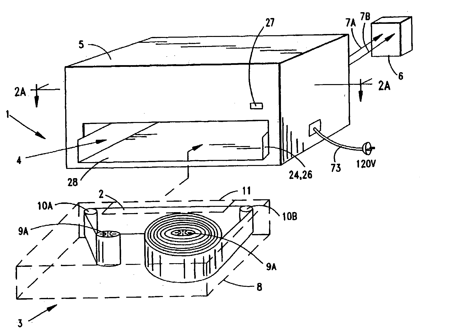
high energy density systems U.S. Pat. No. 5,250,370 to Applicant discloses an improved airmetal FCB
system, wherein the ratio of the recharge
cathode area to the
discharge cathode area is much larger than unity, resulting in a much faster recharge time.
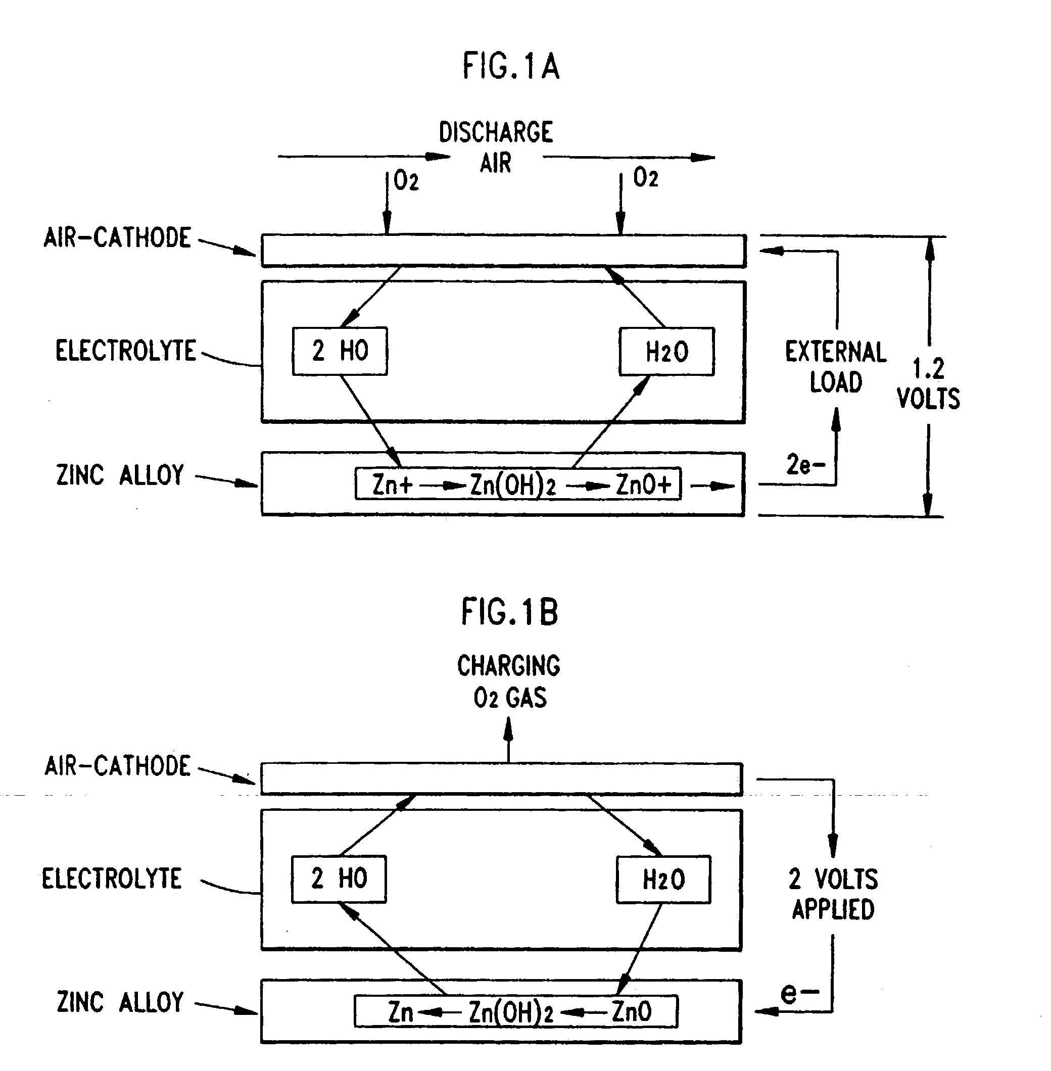
In particular, the supply of energy provided from air-metal FCB systems is inexhaustible because the fuel,
zinc, is plentiful and can exist either as the metal or its
oxide but will never vanish from the earth.
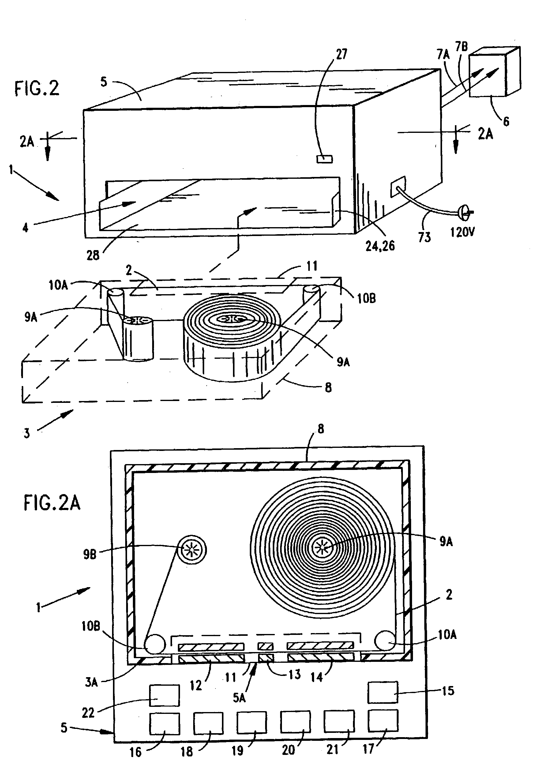
While air-metal FCB technology offers fundamental advantages of FCB systems over conventional fuel cell systems, prior art air-metal FCB systems suffer from a number of shortcomings and drawbacks.
In prior art air-metal FCB systems, the physical configuration of the metal (e.g.
Zinc) fuel in relation to the air-pervious cathode structure has not enabled the design or manufacture of electrochemical power supplies with ultra-compact construction required for portable electronic devices, such as radios, cellular-phones,
laptop computers, and the like.
In prior art air-metal FCB systems, the mechanisms used to supply metal fuel to the air-pervious cathode structure have been unsuitable for meeting the electrical energy requirements of various classes of users.
For example, in connection with low power consuming devices, such as cellular phones and
laptop computers, it has not been possible to design or make air-metal FCB systems of ultra-compact design.

