Apparatus for high-throughput ion beam-assisted deposition (IBAD)

a technology of ion beam and apparatus, which is applied in the field of apparatus for high-throughput ion beam assisted deposition (ibad), can solve the problems of severely restricting the throughput of the process, low deposition rate, etc., and achieves the effects of maximizing throughput, optimum thin film quality, and sufficient width

Inactive Publication Date: 2004-12-23
SUPERPOWER INC
View PDF11 Cites 42 Cited by
  • Summary
  • Abstract
  • Description
  • Claims
  • Application Information

AI Technical Summary

Problems solved by technology

However, to date only short samples of the HTS tape used in the manufacture of next-generation HTS wires have been fabricated at high performance levels.
The low deposition rate severely restricts the throughput of the process.

Method used


Image

  • Apparatus for high-throughput ion beam-assisted deposition (IBAD)
  • Apparatus for high-throughput ion beam-assisted deposition (IBAD)
  • Apparatus for high-throughput ion beam-assisted deposition (IBAD)

Examples


Embodiment Construction

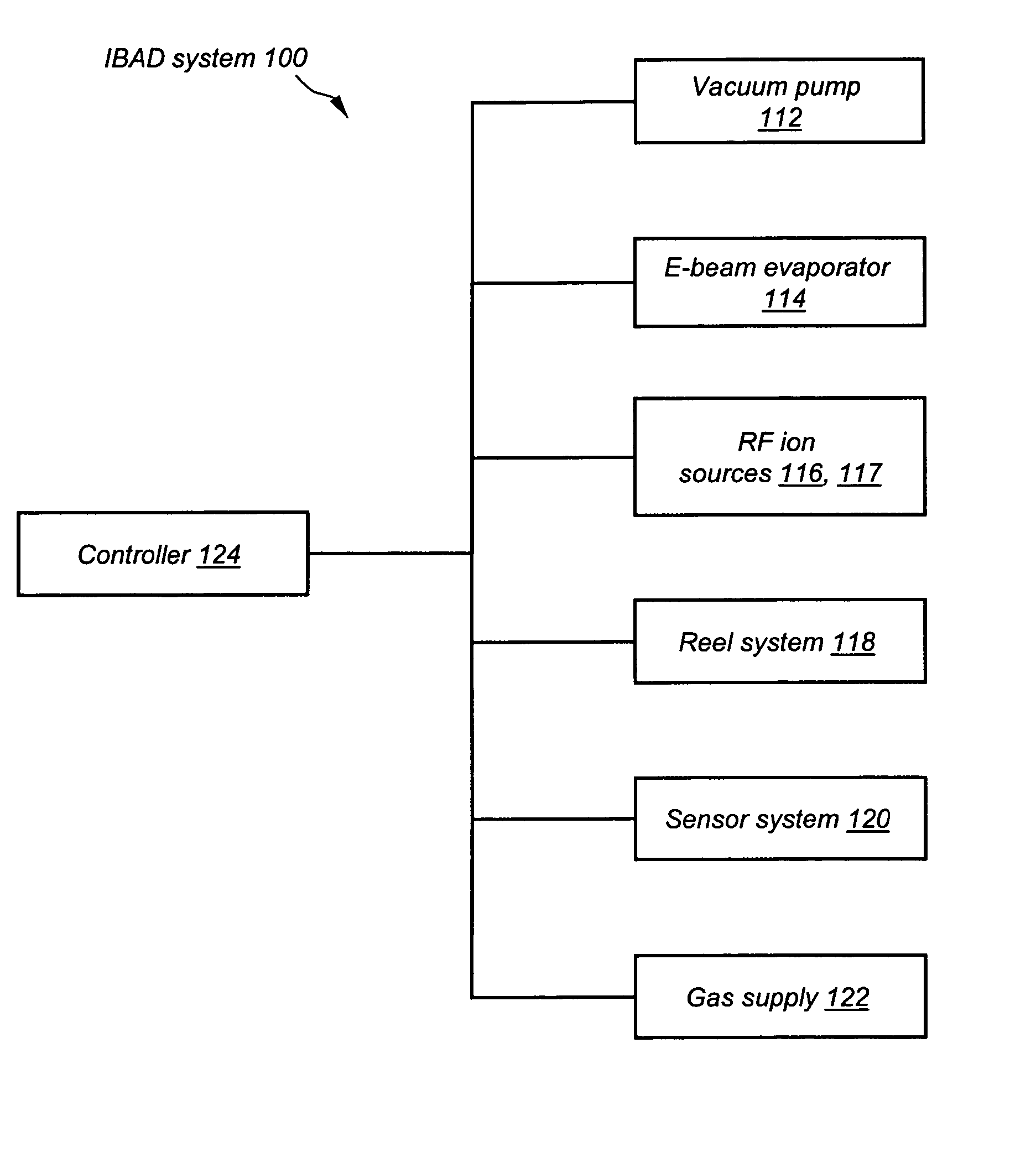
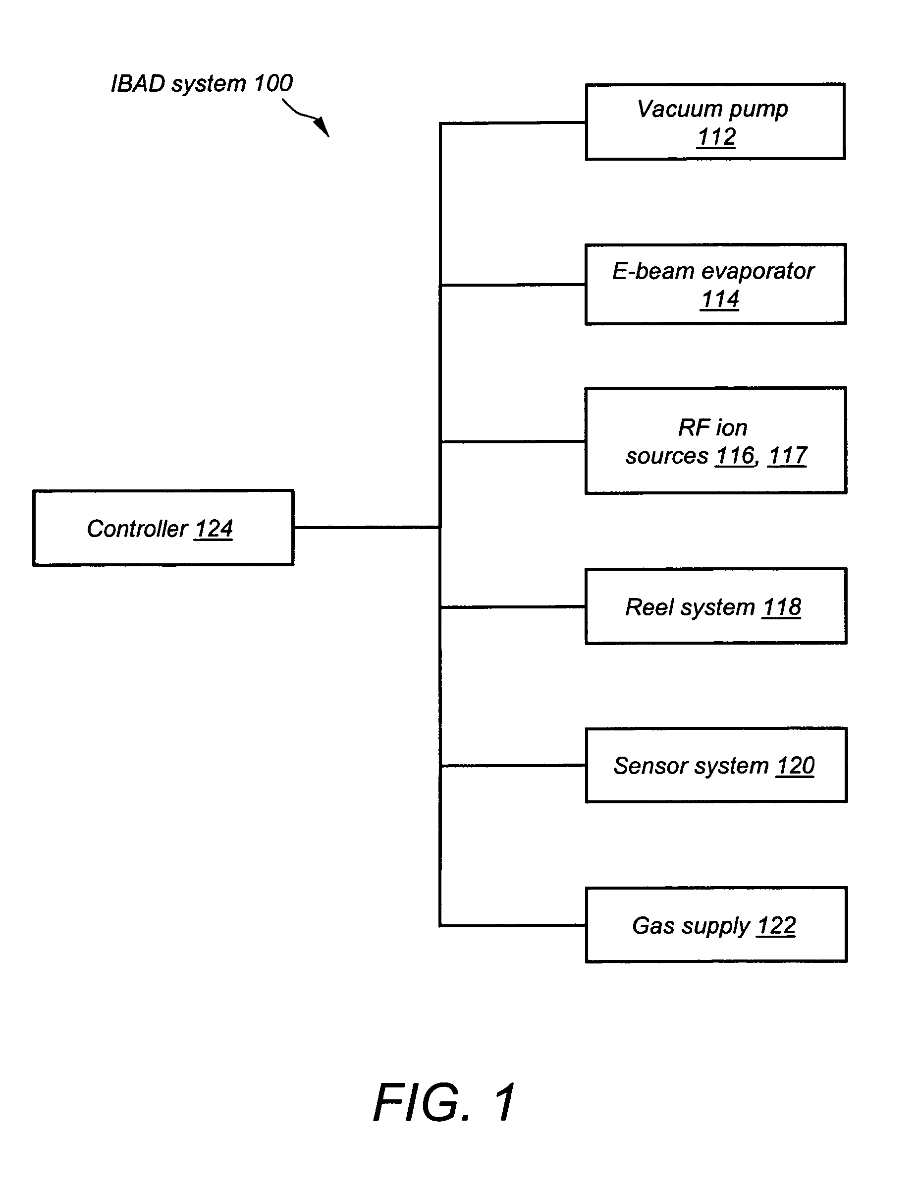
[0016] FIG. 1 illustrates a high-level block diagram of an IBAD system 100 in accordance with the invention, depicting the functional relationships between each subsystem. The IBAD system 100 includes a plurality of subsystems as follows:

[0017] a commercially available vacuum pump 112 that is capable of maintaining a vacuum of pressure in the order of magnitude of 10.sup.-5 Torr. One example of such a pump is an APD Cryogenics, Marathon 16 cryopump.

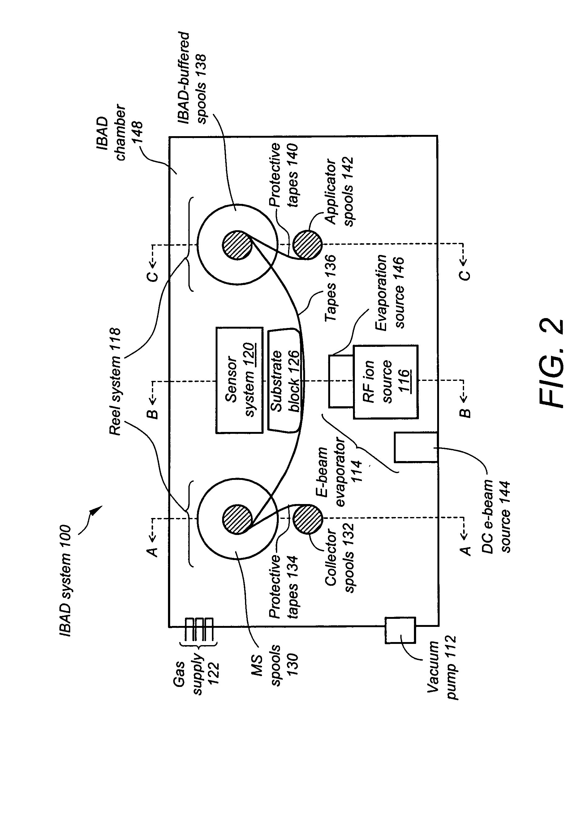
[0018] an energy source 114 such as an electron beam (e-beam) evaporator or ion beam or magnetron sputtering source, that produces a vapor of depositing material via the erosion of the surface of a solid source. The e-beam evaporator 114 assembly includes elements that are described in reference to FIG. 2.

[0019] a first RF ion source 116 and a second RF ion source 117 that are commercially available ion sources such as a pair of Veeco-Ion Tech, RF 6* 22 linear sources using a voltage of 1500 volts and having a power rating of 500 W;

[0020]...


PUM

PropertyMeasurementUnit
pressureaaaaaaaaaa
incident anglesaaaaaaaaaa
incident angleaaaaaaaaaa

Abstract

Disclosed is an ion beam-assisted deposition system that includes a bi-lateral RF ion source system that, when used in conjunction with an electron beam, magnetron or ion beam evaporator assembly, creates a deposition zone of sufficient width to enable simultaneous deposition onto a plurality of parallel-arranged translating metal substrate tapes. The arrangement of the bilateral RF ion source is such that a pair of RF ion sources is arranged on opposite sides of an evaporation source in such a manner that a pair of ion beams is directed toward a translating set of parallel-arranged substrate tapes at incident angles of, for example, 55 degrees.

Description

[0001] The present invention relates to an ion beam-assisted deposition (IBAD) system and method of utilizing such a system. More specifically, the present invention relates to large-scale ion beam-assisted deposition of thin films, such as the buffer layers of high-temperature superconducting (HTS) tapes.[0002] Wire forms the basic building block of the world's electric power system, including transformers, transmission and distribution systems, and motors. The discovery of revolutionary HTS compounds in 1986 led to the development of a radically new type of wire for the power industry; this discovery is the most fundamental advance in wire technology in more than a century. However, to date only short samples of the HTS tape used in the manufacture of next-generation HTS wires have been fabricated at high performance levels. In order for HTS technology to become commercially viable for use in the power generation and distribution industry, it will be necessary to develop technique...

Claims


Application Information

Patent Timeline
Patent Type & Authority Applications(United States)
IPC IPC(8): B05D5/12C23C14/22C23C14/32C23C14/54C23C14/56C23C16/00H01L39/24H02J
CPCC23C14/22C23C14/32C23C14/54Y10T29/49014H01J2237/3142H01L39/2461C23C14/562H10N60/0632
Inventor SELVAMANICKAM, VENKATSATHIRAJU, SRINIVAS
Owner SUPERPOWER INC
Why Eureka
Try Eureka