Stent delivery catheter

a technology of stent and catheter, which is applied in the field of stent delivery catheter, can solve the problems of insufficient expansion high probability of restnosis at the narrowed area, and increase the thickness of the stent at this portion, so as to effectively prevent the stent 11 from moving or falling, and increase the outer diameter

Inactive Publication Date: 2004-12-30
KANEKA CORP
View PDF11 Cites 84 Cited by
  • Summary
  • Abstract
  • Description
  • Claims
  • Application Information

AI Technical Summary

Benefits of technology

0118] Various embodiments of the stent delivery catheter according to a second invention will now be described in detail with reference to the drawings. As with the first invention, the stent delivery catheter of the second invention may also be of the over-the-wire type shown in FIG. 1 or the rapid exchange type shown in FIG. 2.
0119] In the stent delivery catheter of the second invention, the basic structure of the catheter, the method for making the balloon 1, materials of the outer tube 2, the inner tube 3, and the hub 9, the method for joining the balloon 1 with the outer tube 2 and the inner tube 3, and the like are identical to those of the first invention. Thus, the description regarding these features is omitted, and only the features different from the first invention will be described below in detail.
0120] The undeployed stent 11 is mounted on the collapsed balloon 1 that satisfies both the relationship (T1/T2)<1.3, wherein T1 represents the thickness of a near-center portion of the tapered segment 1B at the distal end and T2 represents the thickness of a near-center portion of the straight tubular segment 1A, and the relationship (T3/T2)<1.3, wherein T3 represents the thickness of a near-center portion of the tapered segment 1C at the proximal end and T2 represents the thickness of the near-center portion of the straight tubular segment 1A. In such a case, the outer diameter of the undeployed stent 11 becomes larger than the outer diameters of the straight tubular segment 1A, the tapered segment 1B at the distal end, and the tapered segment 1C at the proximal end of the balloon 1. Accordingly, friction may occur between the stent 11 and the hemostatic valve 13 or the guide catheter 12, and the stent 11 may move on the balloon or may even fall off from the catheter (the same configuration as shown in FIG. 12). Here, the term "near-center portion" means "approximately central portion" and defines the area within the range .+-.1 mm from the true center.
0121] When

Problems solved by technology

Since this portion of the balloon expands into a tapered shape, the expansion of the stent at this portion becomes insufficient.
As a result, it is highly likely that restenosis would occur at the narrowed area.
However, mechanical or thermal damage may be inflicted upon the balloon during the process of heating, pressurizing, and cooling the balloon.
Formation of the high friction coefficient layer on the outer wall of the balloon complicates the manufacturing process and thus produces cost problems.
However, since the two collars are fixed onto portions inside the balloon, the flexibility of the balloon portion is significantly decreased.
A drawback of the balloon catheter of this t

Method used


Image

  • Stent delivery catheter
  • Stent delivery catheter
  • Stent delivery catheter

Examples


example 2

[0098] A sample was prepared as in EXAMPLE 1 except that the outer tube was used as the displacement prevention mechanism at the proximal end of the balloon.

example 3

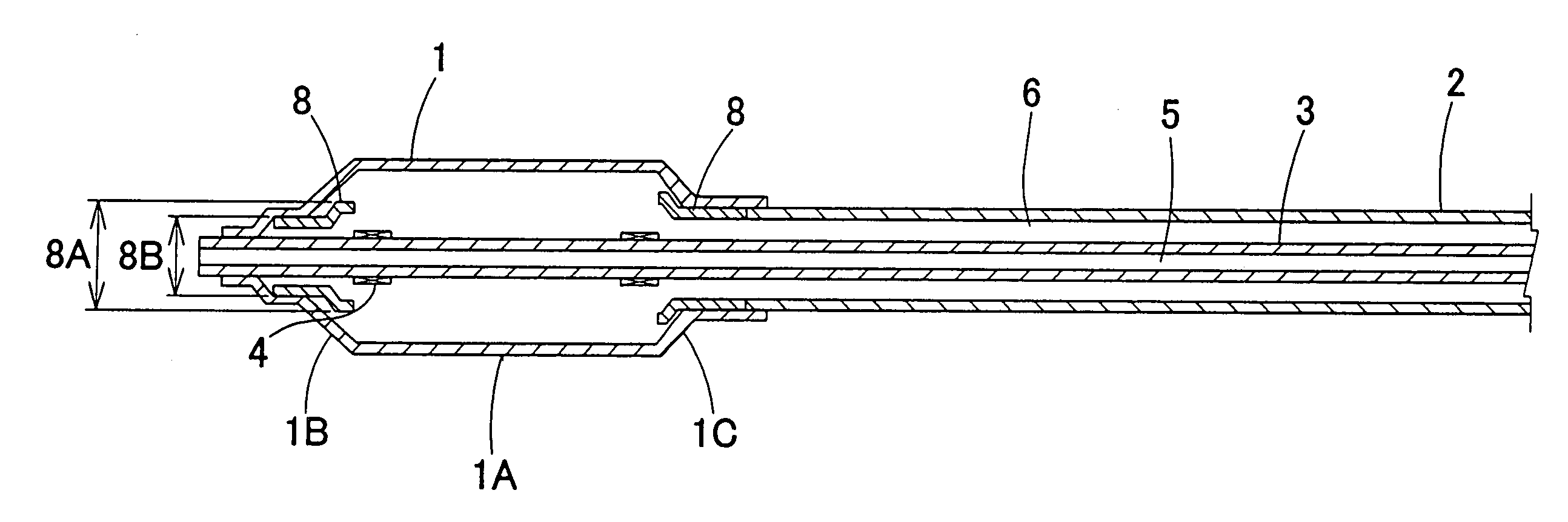
[0099] A sample was prepared as in EXAMPLE 1 with the exception of the following. The same tubular member as in EXAMPLE 1 was used as the displacement prevention mechanism at the distal end of the balloon. The outer diameter of the tubular member was increased to 1.20 mm, and the portion with the increased outer diameter was extended into the balloon tapered segment at the distal end of the balloon. The same tubular member as in EXAMPLE 1 was used as the displacement prevention mechanism at the proximal end of the balloon. The outer diameter of one end of the tubular member was increased to 1.20 mm, and the portion with the increased outer diameter was extended into the balloon tapered segment at the proximal end. Moreover, the inner diameter of the portions of the balloon jointed with the displacement prevention mechanisms was adjusted to 1.25 mm.

[0100] A sample was prepared as in EXAMPLE 1 with the exception of the following. A radiopaque marker (inner diameter: 0.83 mm, outer dia...

example 5

[0102] A sample was prepared as in EXAMPLE 1 except for the following. The same tubular member (first tubular member) as in EXAMPLE 1 was used to form each of the displacement prevention mechanisms at the distal and proximal ends of the balloon. Another tubular member (second tubular member, inner diameter: 0.95 mm, outer diameter: 2.00 mm) prepared by extrusion molding using a polyamide elastomer (trade name: PEBAX7033SA01, manufactured by Elf Atochem) was joined to one end of each first tubular member by melt bonding. The jointed portions were placed in tapered segments at the distal and proximal ends of the balloon, respectively. The inner diameter of the jointed portions of the balloon jointed with the displacement prevention mechanisms were adjusted to 2.05 mm.


PUM


Abstract

The present invention provides a stent delivery catheter that can place a stent in a tortuous narrowed area with good maneuverability while preventing falling or displacement of the stent. The present invention provides a stent delivery catheter for delivering a stent for treating stenosis in a body to a narrowed area. A distal end of the catheter includes a collapsible balloon in a collapsed state and the stent in an undeployed state, the stent being mounted on the outer surface of the collapsed balloon, the balloon having frustoconical tapered segments and a cylindrical straight tubular segment. An inner tube for defining a guidewire lumen extends into the interior of the balloon, and displacement prevention mechanisms for preventing the stent from moving in the longitudinal direction of the stent delivery catheter are affixed to the inner surface of the balloon only. Another aspect of the present invention provides a stent delivery catheter that can prevent the stent from moving in the axis direction of the catheter without requiring additional components or additional steps that complicate the manufacturing process. In this catheter, the thickness T1 of a near-center portion of the distal-end tapered segment and the thickness T2 of a near-center portion of the straight tubular segment satisfy a predetermined relationship, and the thickness T3 of a near-center portion of the proximal-end tapered segment and the thickness T2 of the near-center portion of the straight tubular segment satisfy a predetermined relationship. In this manner, the distal-end and proximal-end tapered segments in the collapsed state prevent the movement of the stent. The present invention also provides a preferable RX balloon catheter, i.e., a stent delivery catheter, having improved maneuverability and enhanced responsiveness for expansion and contraction of the balloon without complicating the manufacturing process or increasing the cost.

Description

[0001] The present invention relates generally to delivery catheters for introducing and placing stents for expanding narrowed areas of blood vessels, esophagi, tracheae, urethrae, bile ducts, etc. In particular, it relates to a delivery catheter for introducing and placing a stent to a narrowed area of a coronary artery.[0002] Stents, which are left in narrowed areas of vessels such as blood vessels, esophagi, tracheae, urethrae, and bile ducts, are widely used devices for efficiently maintaining lumina. A stent is folded to be introduced into a vessel and is placed at a predetermined narrowed area. Subsequently, the stent is deployed to a predetermined size and left in that location.[0003] Stents are roughly categorized into two types according to the mechanism for expanding stents to predetermined sizes. One type is of a self-expandable stent variety. Stents of this type are composed of shape-memory alloys and do not require mechanical stent expansion. The other type is of a ball...

Claims


Application Information

Patent Timeline
IPC IPC(8): A61F2/958A61M25/12
CPCA61F2/958A61F2002/9586A61M2025/0063A61M2025/0183A61M29/00
Inventor NISHIDE, TAKUJIMIKI, SHOGO
Owner KANEKA CORP
Why Eureka
Try Eureka