Motor control device

a control device and motor technology, applied in the direction of motor control, engine starter, electric generator control, etc., can solve the problems of increasing the switching loss as a whole, reducing so as to achieve the effect of increasing the efficiency of rectification

Inactive Publication Date: 2005-01-06
HITACHI LTD
View PDF12 Cites 37 Cited by
  • Summary
  • Abstract
  • Description
  • Claims
  • Application Information

AI Technical Summary

Benefits of technology

With the arrangement set forth above, the power running control can be performed w

Problems solved by technology

In the case of driving an AC motor based on the PWM control, high switching frequency increases the number of times of switching to be made for a certain time and hence increases a switching loss as a whole.
Also, because of a high switching speed, a ripple of DC voltage is increased and a smoothing capacitor having a large capacity is required to suppress the ripple, thus resulting in a larger size of a motor control device.
Since an induced voltage of the AC motor must be held lower than the voltage capable of being controlled by the motor control device, the field intensity is weakened in the range of high rotation speeds.
This requires an additional cur

Method used


Image

  • Motor control device
  • Motor control device
  • Motor control device

Examples


Embodiment Construction

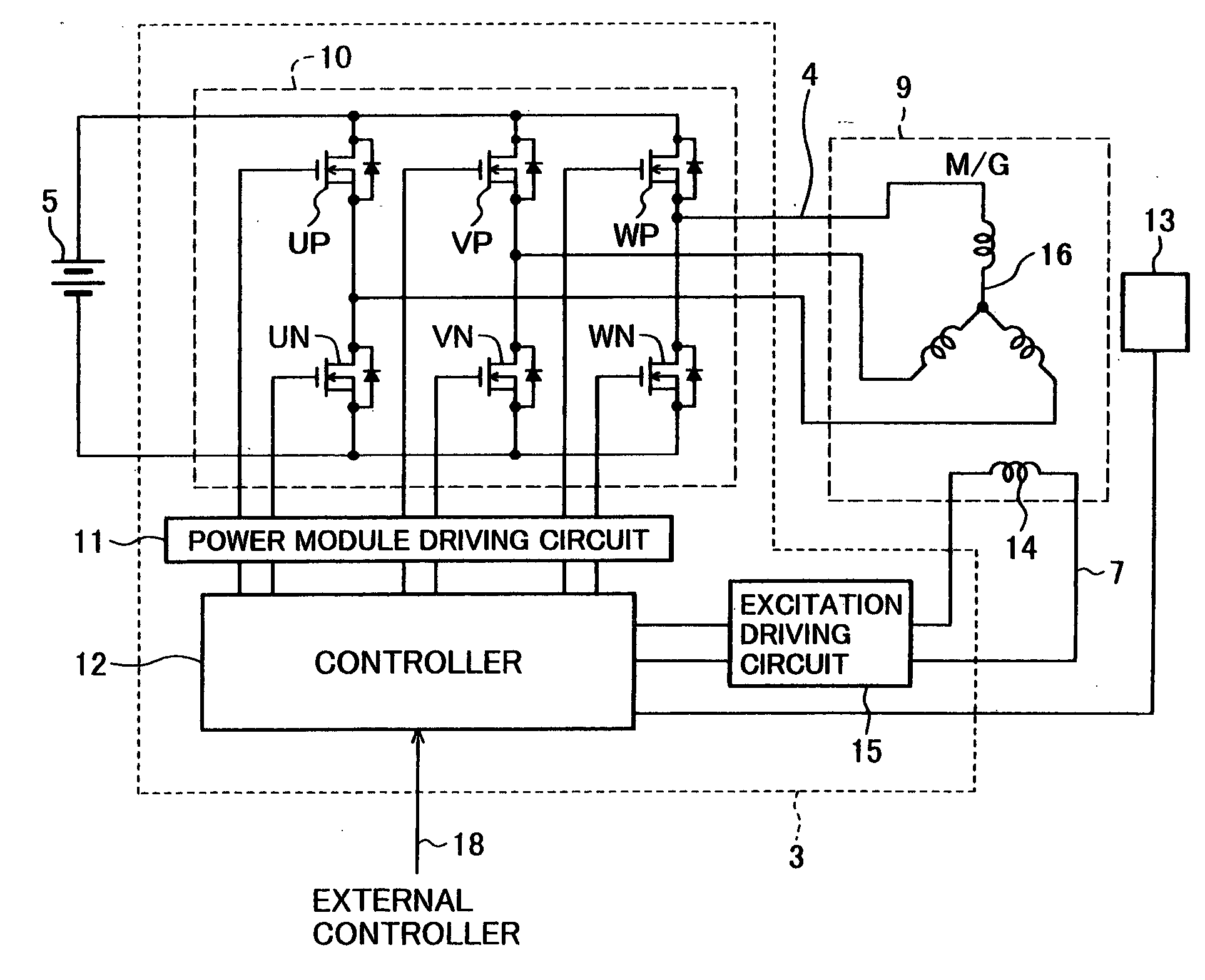
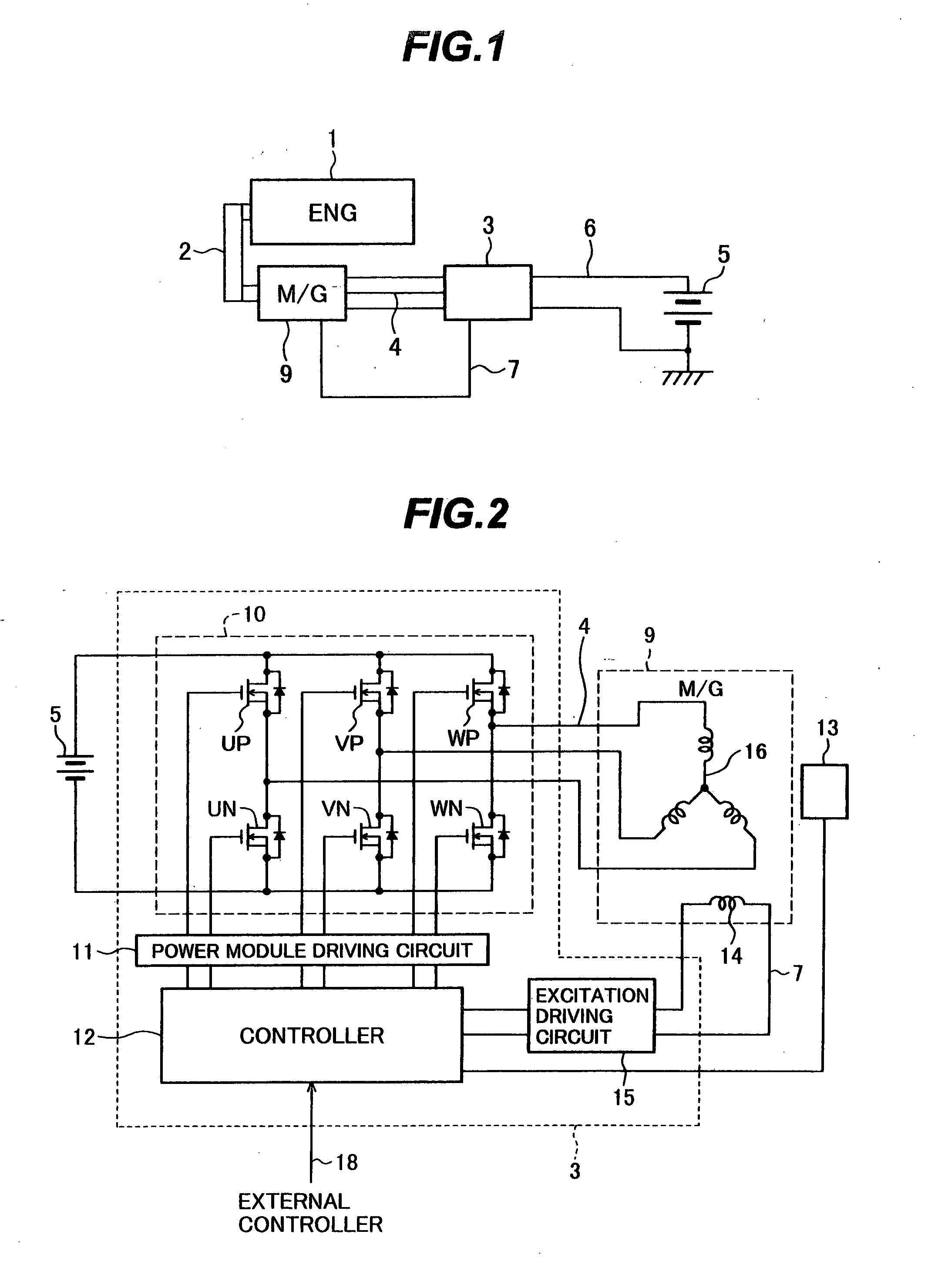
Embodiments of the present invention will be described below with reference to the accompanying drawings. FIG. 1 shows the construction of a driving system of a vehicle mounted with a motor control device for a vehicle according to one embodiment of the present invention. As shown in FIG. 1, the driving system of the vehicle comprises an internal combustion engine 1, an AC motor (motor / generator) 9, a motor control device 3, and a DC power source (battery) 5. A crankshaft of the internal combustion engine 1 and an output shaft of the AC motor 9 are coupled to each other through a power transmitting means 2 such as a belt. Also, the AC motor 9 and the motor control device 3 are connected to each other by 3-phase power cables (output lines) 4 and an excitation cable 7. The motor control device 3 is connected to the DC power source (battery) 5 via DC power cables (power source lines) 6.

The motor control device 3 operates as an inverter circuit for converting a DC power from the DC p...


PUM


Abstract

The invention is intended to provide a control device for a vehicular AC motor, which has higher efficiency of voltage utilization in a power running mode and has higher efficiency of electricity generation in an electricity generation mode. The motor control device comprises rectifying devices and switching devices for three phases, which are connected between a DC power source and armature coils of an AC motor operatively coupled to an internal combustion engine. The motor control device has the inverter function of converting a DC power from the DC power source into an AC power and supplying the AC power to the armature coils, and the converter function of converting an AC power generated by the AC motor into a DC power and supplying the DC power to the DC power source. Rectangular-wave driving control of applying rectangular wave voltages to the armature coils of the AC motor is performed when the AC motor is operated for power running, and synchronous rectification control for making synchronous rectification of the AC power generated by the AC motor is performed when the AC motor is operated for electricity generation.

Description

BACKGROUND OF THE INVENTION 1. Field of the Invention The present invention relates to a control device for a vehicular AC motor, and more particularly to a motor control device for controlling outputting of power (i.e., power running) and generation of electric power (i.e., electricity generation). 2. Description of the Related Art As a control method for a vehicular AC motor, there is known PWM. (Phase Width Modulation) control for switching a device with a high-frequency PWM signal and changing the phase of a current flowing through an armature coil of the AC motor relative to an induced voltage of the AC motor, thereby performing power running or electricity generation. JP,A 2000-197204 discloses rectangular-wave driving control for applying, to an armature coil of an AC motor, a rectangular wave voltage each phase of which is changed over per half cycle (180°), and changing the phase of a current flowing through the armature coil relative to an induced voltage of the AC mo...

Claims


Application Information

Patent Timeline
IPC IPC(8): F02N11/04B60L50/15F02N11/08H02M7/797H02P9/08
CPCF02N11/04F02N11/0859H02P9/08H02M7/797F02N2011/0896
Inventor GOTO, KOSEIINNAMI, TOSHIYUKIFUJINO, SHINICHISAKURAI, YOSHIMIINABA, MASAMITSUIWAMURA, MASAHIROSHIRAKAWA, SHINJISAKANO, JUNICHIHASHIMOTO, KEITATSUCHIYA, MASANORI
Owner HITACHI LTD
Why Eureka
Try Eureka