MEMS mirror device and optical disk apparatus

a mirror device and optical disk technology, applied in the direction of instruments, recording information storage, disposition/mounting of heads, etc., can solve the problems of unstable control system to make correct focusing difficult, actuators may not often make tracking control sufficiently stable, and insufficient tracking control stable, etc., to improve electromagnetic conversion efficiency, improve the operation characteristics of the mems mirror, and increase the effect of magnetic field

Active Publication Date: 2005-01-06
FUNAI ELECTRIC CO LTD
View PDF0 Cites 43 Cited by
  • Summary
  • Abstract
  • Description
  • Claims
  • Application Information

AI Technical Summary

Benefits of technology

[0022] Moreover, the electromagnetic coil is wired like eight-figure, and the permanent magnet is magnetized to generate a magnetic field like closed loop in a predetermined portion of the electromagnetic coil. Thereby, the intensity of magnetic field in the predetermined portion of the electromagnetic coil is stabilized, and the electromagnetic conversion efficiency is improved, whereby the operation characteristics of the MEMS mirror are improved.
[0023] Also, the resonance peak of the MEMS mirror device is remarkably smaller than the conventional MEMS mirror device, whereby the stable tracking control is enabled by providing the MEMS mirror in the optical disk apparatus.

Problems solved by technology

And when the natural vibration mode is excited at the natural frequency to generate resonance, a control system is unstable to make the correct focusing difficult.
By the way, along with the higher density of the recording medium in recent years, the track pitch (interval between track grooves) is smaller (e.g., 1. m or less), and there is an increasing need for the finer tracking control, whereby the actuator may not often make the tracking control sufficiently.
However, the resonance peak amount of the conventional MEMS mirror device is about 30 dB, so that the control system is unstable at this resonance frequency, resulting in a problem that the stable tracking control is not made.

Method used


Image

  • MEMS mirror device and optical disk apparatus
  • MEMS mirror device and optical disk apparatus
  • MEMS mirror device and optical disk apparatus

Examples


first embodiment

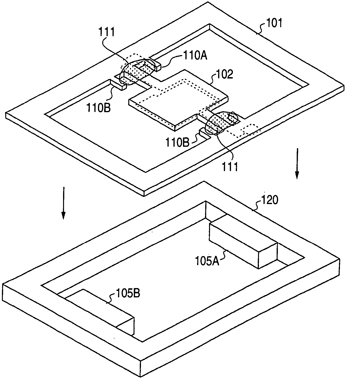
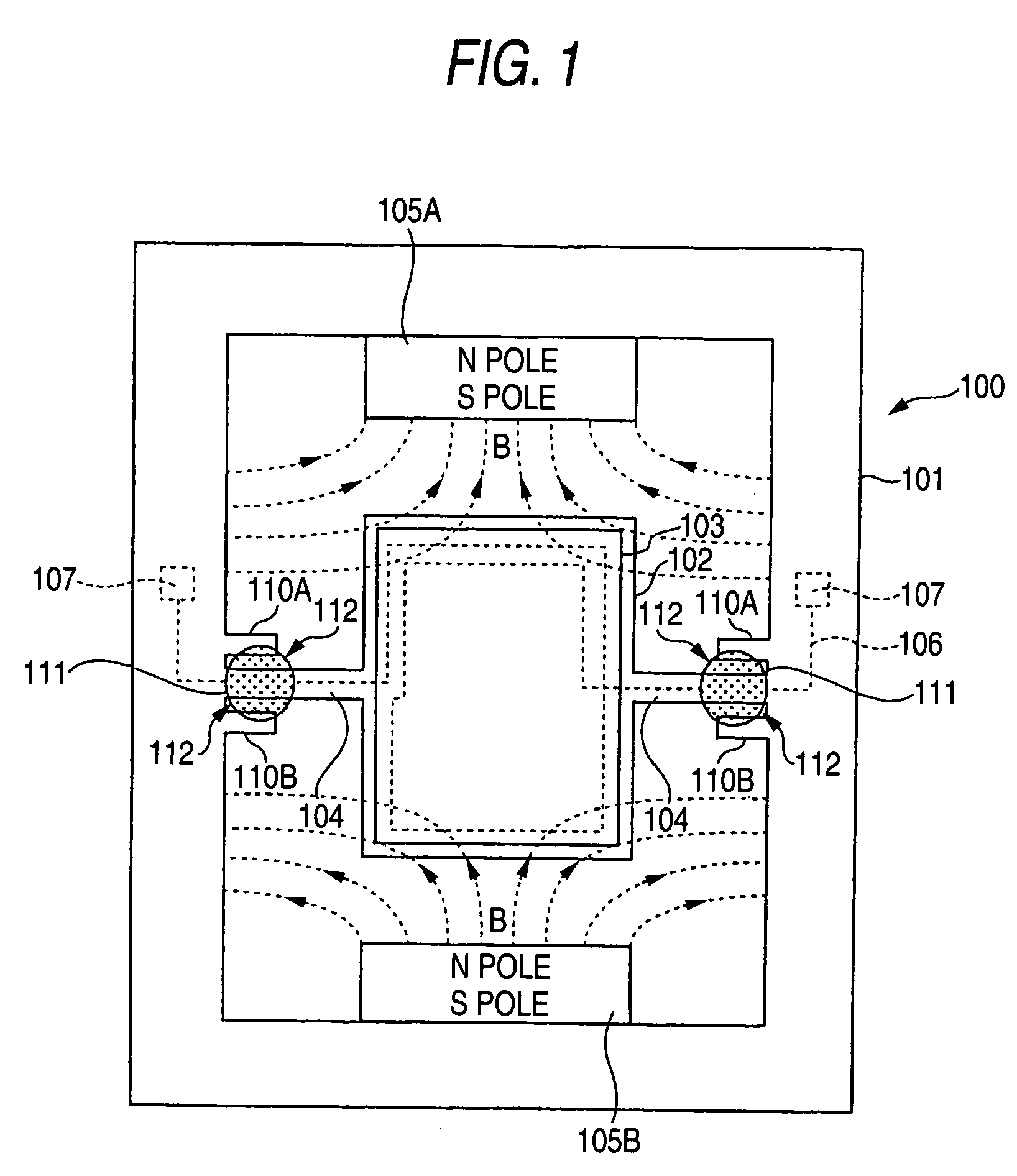
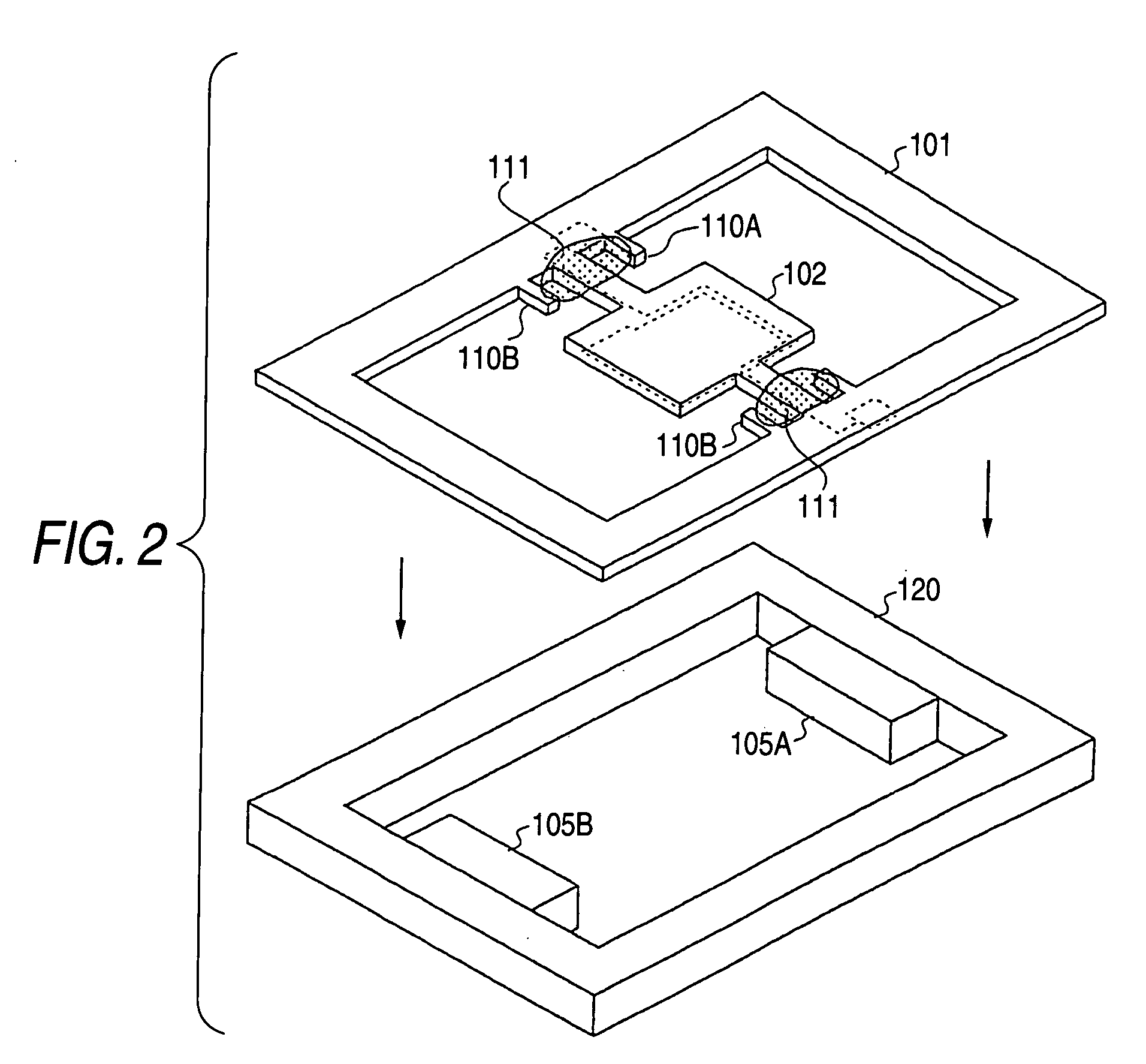
[0032]FIG. 1 is an upper view showing the schematic constitution of an MEMS mirror device 100 according to a first embodiment of the invention. FIG. 2 is an exploded perspective view thereof. FIGS. 3A and 3B is an enlarged view of a connecting portion between a first frame 101 and a hinge 104, in which FIG. 3A shows a state before forming an elastic member 111 and FIG. 3B shows a state after forming the elastic member 111.

[0033] As shown in FIGS. 1 to 3B, a mirror unit 102 is connected via two hinges 104, 104 inside the first frame 101, and a second frame 102 is provided with the permanent magnets 105A, 105B inwardly of the side parallel to the hinge 104. The MEMS mirror device of this embodiment consists of the first frame 101 and the second frame 102 that are jointed.

[0034] The first frame 101 has two protruding portions 110A, 110B spaced at a regular interval and disposed on both sides of the connecting portion between the frame 101 and the hinge 104. And an elastic member 111 ...

second embodiment

[0046]FIG. 5 is an upper view showing the schematic constitution of the MEMS mirror device 100 according to a second embodiment of the invention.

[0047] The MEMS mirror device of the second embodiment is the same as that of the first embodiment, except for the wiring of the electromagnetic coil 106 and the constitution of the permanent magnet 105. That is, though the electromagnetic coil 106 is wired around the peripheral part of the mirror unit in the first embodiment, the electromagnetic coil 106 is wired like eight-figure in the second embodiment. The coil wiring is actually the multiple wiring but the single wiring in FIG. 5.

[0048] Also, though the magnetic field B generated by the permanent magnet 105 is open in the first embodiment, the magnetic field B′ generated by the permanent magnet 105 is closed (closed loop) in the second embodiment. That is, the permanent magnet is magnetized so that both the N pole and S pole appear in the long side direction of the permanent magnet ...


PUM

PropertyMeasurementUnit
frequencyaaaaaaaaaa
frequencyaaaaaaaaaa
magnetic fieldaaaaaaaaaa

Abstract

A MEMS mirror device includes a rectangular frame, a mirror unit having a reflecting portion on one face thereof and connected via the hinges inside the frame, and a drive unit for tilting the mirror unit around the hinges as the axis, wherein the frame has two protruding portions spaced at a regular interval and extending into the frame on both sides of a connected portion with the hinge, and an elastic member is provided to bridge the hinge between two protruding portions.

Description

BACKGROUND OF THE INVENTION [0001] 1. Field of the Invention [0002] The present invention relates to an MEMS (Micro Electro Mechanical System) mirror device constituted in small size employing the MEMS technique and an optical disk apparatus having the MEMS mirror device. [0003] 2. Description of the Related Art [0004] The conventional optical disk apparatus includes a light source (semiconductor laser: LD), an objective lens for focusing a laser beam from the light source onto the surface of a recording medium such as an optical disk, a photodetector for detecting various kinds of signal from the light reflected from the recording medium, a beam splitter for leading the laser beam to proceed on a predetermined route, a collimator lens for transforming laser beam into a parallel light and a condensing lens for condensing the parallel light. [0005] Also, the objective lens is secured to an actuator for making the focusing control for focusing a focusing point (light spot) of laser be...

Claims


Application Information

Patent Timeline
Patent Type & Authority Applications(United States)
IPC IPC(8): G02B26/08G11B7/09G11B7/135G11B7/1362
CPCG11B7/1362G02B26/085B81B3/0045B81B2203/0109B81B2203/0154
Inventor MATSUI, TSUTOMU
Owner FUNAI ELECTRIC CO LTD
Why Eureka
Try Eureka