CPP spin-valve element

a technology of spin-valve elements and magnetic fields, which is applied in the field of magnetic field spin-valve elements, can solve the problems of low resistance change compared to the cip structure, and achieve the effects of low current, high resistance, and high output signal

Inactive Publication Date: 2005-01-06
UNIVERSITY OF ALABAMA +1
View PDF12 Cites 56 Cited by
  • Summary
  • Abstract
  • Description
  • Claims
  • Application Information

AI Technical Summary

Benefits of technology

[0012] An objective of the present invention is to provide a spin-valve element of a CPP structure that has a high resistance and which generates a high output signal with a low current.

Problems solved by technology

However, the drawback in the ordinary CPP structure is the fact that only a very low resistance change is obtainable compared to the CIP structure.

Method used


Image

  • CPP spin-valve element
  • CPP spin-valve element
  • CPP spin-valve element

Examples


Embodiment Construction

[0032] FIGS. 3(a), 3(b), and 3(c) illustrate the contour mappings, calculated by simulation, of the total resistance RP for the parallel configuration (the configuration in which the magnetizations of the free and pinned layer structures are parallel to each other), the difference between the resistances between the parallel and anti-parallel configurations (i.e., the magnetoresistance ΔR), and the GMR ratio as a function of the location of the two CC-layers, CC-layer 1 and CC-layer 2. The simulation was performed by using a resistor network model. An example of the resistor network model is shown schematically in FIG. 4.

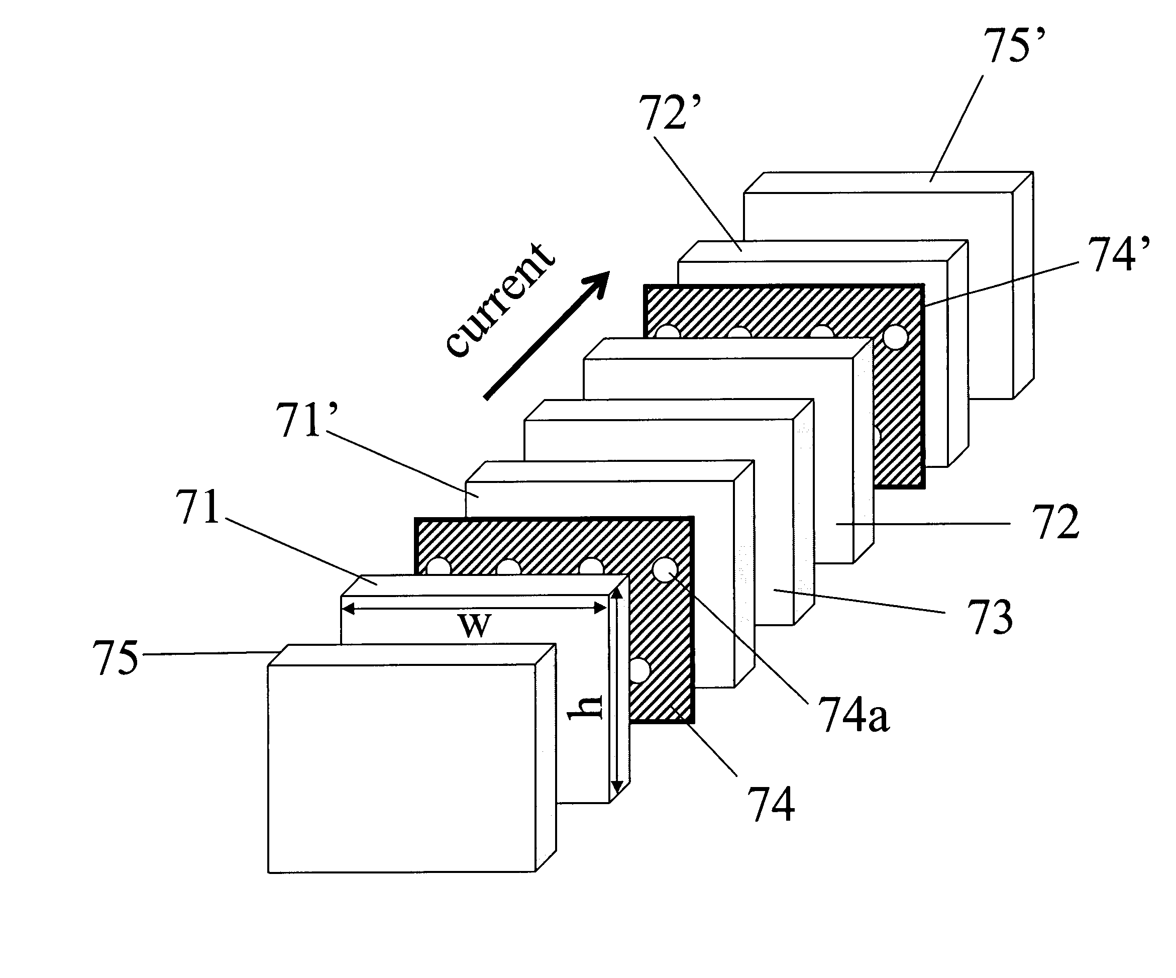
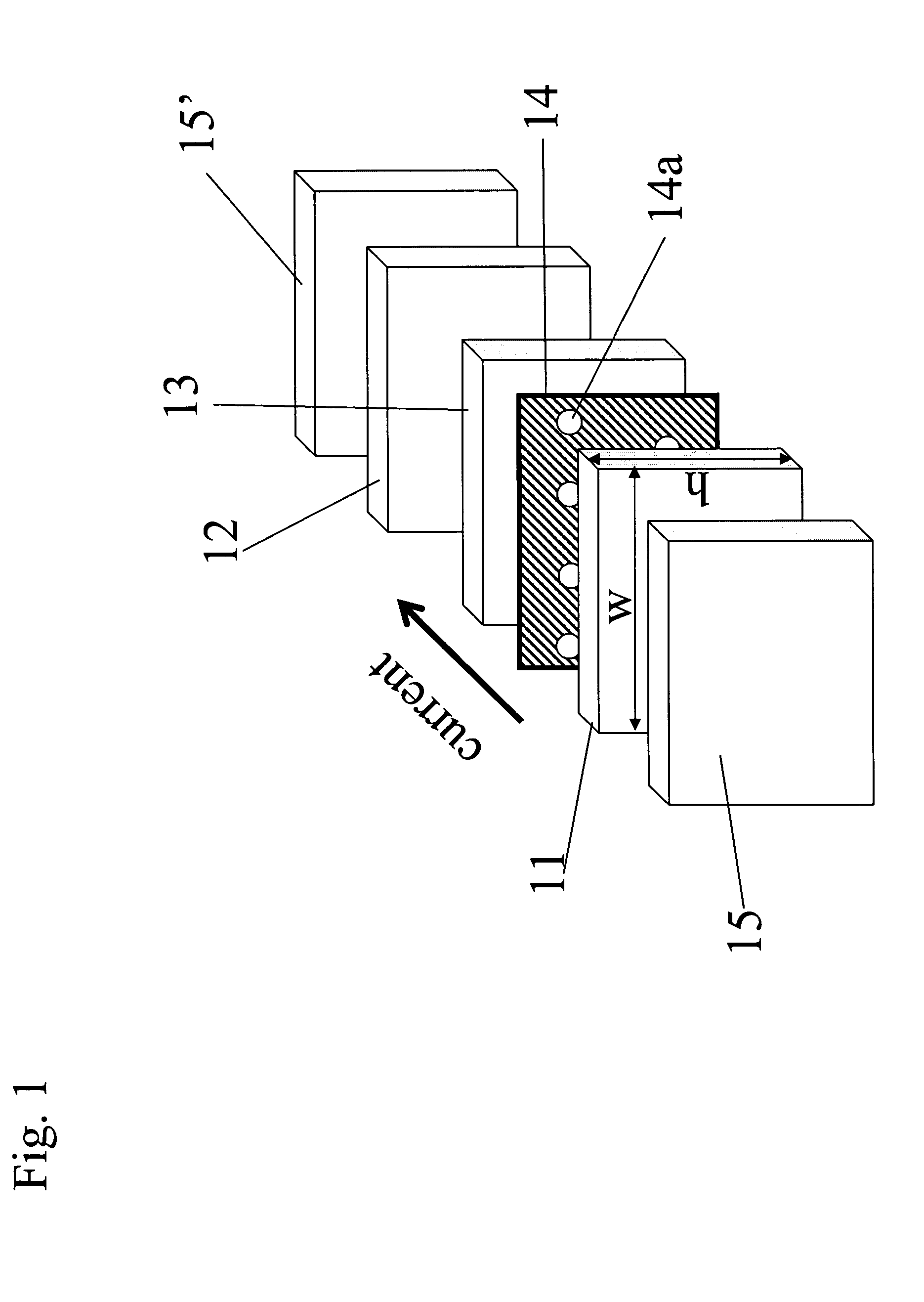
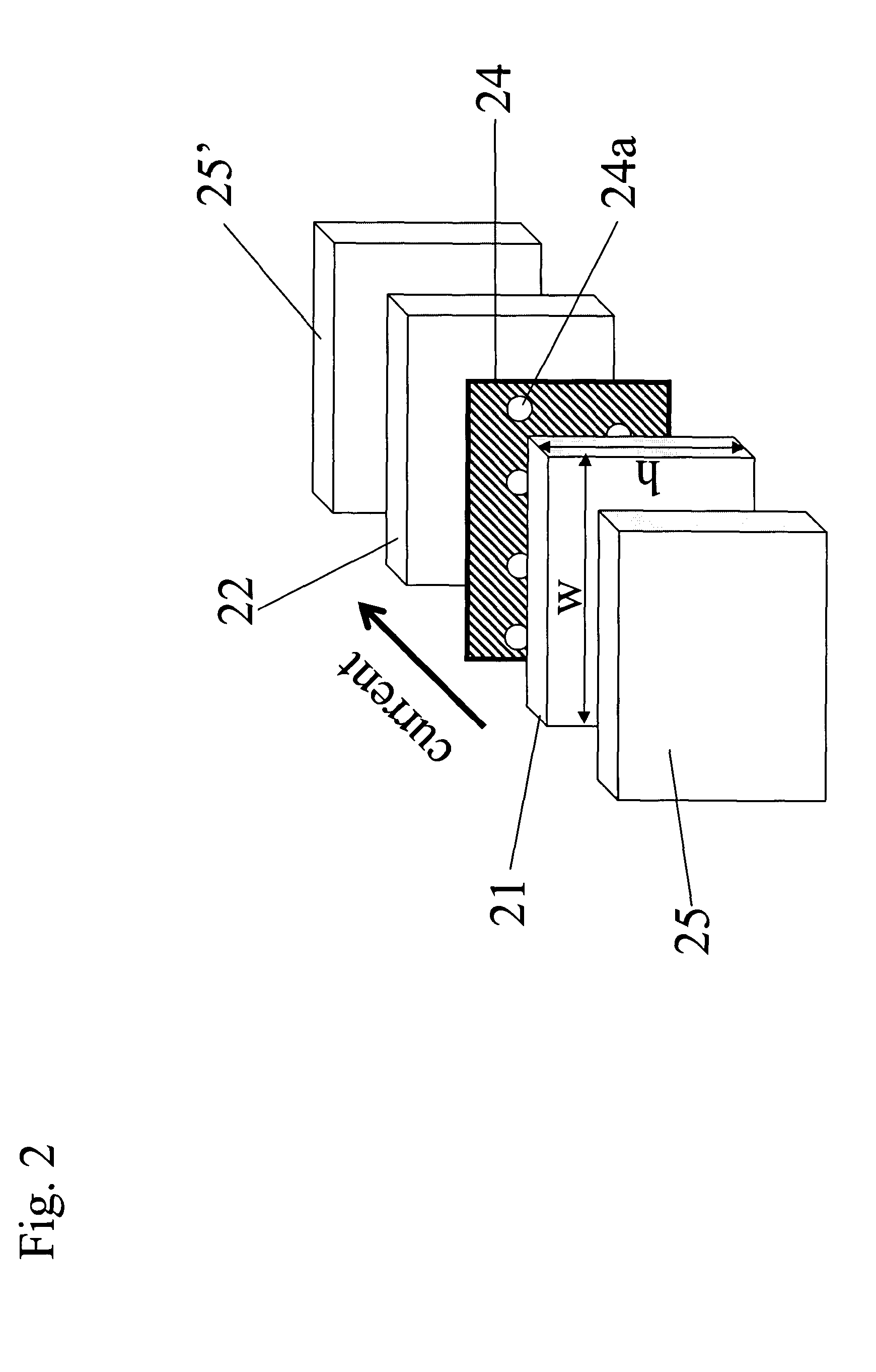
[0033] The plane of the spin-valve element was set in the x-z plane. Here 41 is a ferromagnetic free layer. 42a and 42b are a ferromagnetic layer and an antiferromagnetic layer, respectively, including a pinned layer structure and a pinned layer including a pinning layer, respectively. 43 is a non-magnetic conducting spacer layer. 44 and 44′ are CC-layers each havi...


PUM

PropertyMeasurementUnit
widthaaaaaaaaaa
thickaaaaaaaaaa
sizeaaaaaaaaaa

Abstract

A CPP spin-valve element formed on a substrate including a free layer structure including at least one ferromagnetic layer and a pinned layer structure including at least one ferromagnetic layer. The free layer is magnetically softer than the pinned layer. A thin non-magnetic spacer layer structure configured to separate the free layer and the pinned layer is provided in order to prevent a magnetic coupling between the free and pinned layer structures, and to allow an electric current to go there through. At least two current-confining (CC) layer structures including at least two parts having significantly different current conductivities are incorporated therein.

Description

BACKGROUND OF THE INVENTION [0001] 1. Field of the Invention [0002] This invention, in general, relates to the field of magnetoresistive spin-valve (SV) elements. More specifically, the present invention relates to current perpendicular-to-the-plane (CPP) spin-valve device configurations, applicable as a magnetic non-volatile mass-memory called (MRAM) and / or as a magnetic transducer or “head” for reading information signals recorded on a magnetic medium. [0003] 2. Description of Prior Art [0004] The related art, e.g., U.S. Pat. No. 5,159,513, discloses a magnetic transducer which is sometimes referred to as a spin-valve magnetoresistive sensor. A spin-valve element includes at least two ferromagnetic layers having different magnetic field sensitivity. The ferromagnetic layer having the higher sensitivity is referred to as the “free layer” and the other ferromagnetic layer is referred to as the “pinned layer.” The resistance of the spin valve element is a function of the angle betwee...

Claims


Application Information

Patent Timeline
Patent Type & Authority Applications(United States)
IPC IPC(8): G11B5/39G11B5/127H01F10/32H01F41/18H01F41/20H01L21/8246H01L27/105H01L43/08H01L43/10
CPCG11B5/1278
Inventor FUJIWARA, HIDEONAGASAKA, KEIICHIZHAO, TONGBULTER, WILLIAM H.VELEV, JULIANBANDYOPADHYAY, AMRIT
Owner UNIVERSITY OF ALABAMA
Why Eureka
Try Eureka