

Carbon nanotube particulates, compositions and use thereof
a carbon nanotube and particulate technology, applied in the manufacture of electrode systems, metal/metal-oxide/metal-hydroxide catalysts, electric discharge tubes/lamps, etc., can solve the problems of increasing defects, -wall carbon nanotubes, 4 nm, and the lik
- Summary
- Abstract
- Description
- Claims
- Application Information
AI Technical Summary
Benefits of technology
Problems solved by technology
Method used
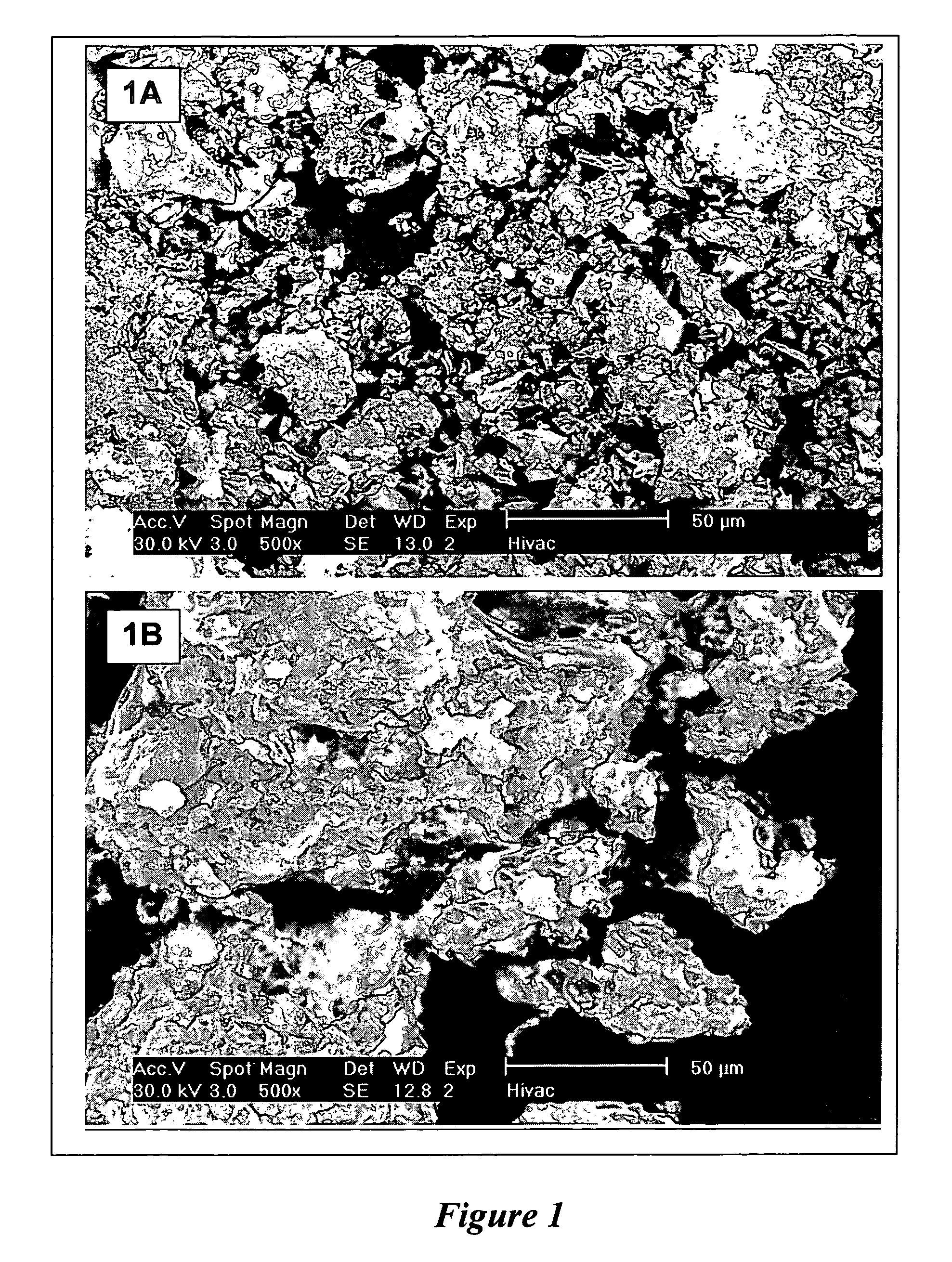
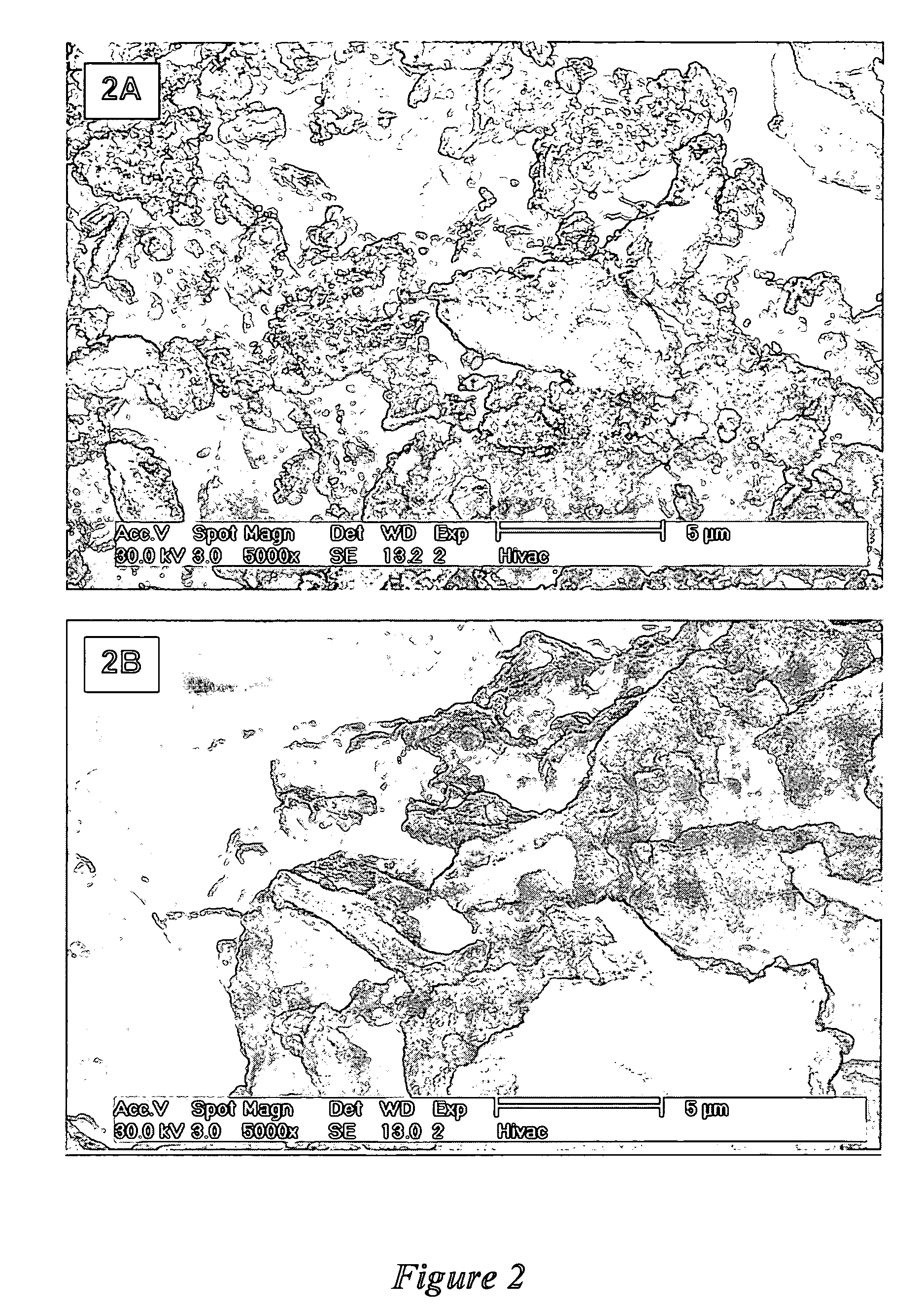
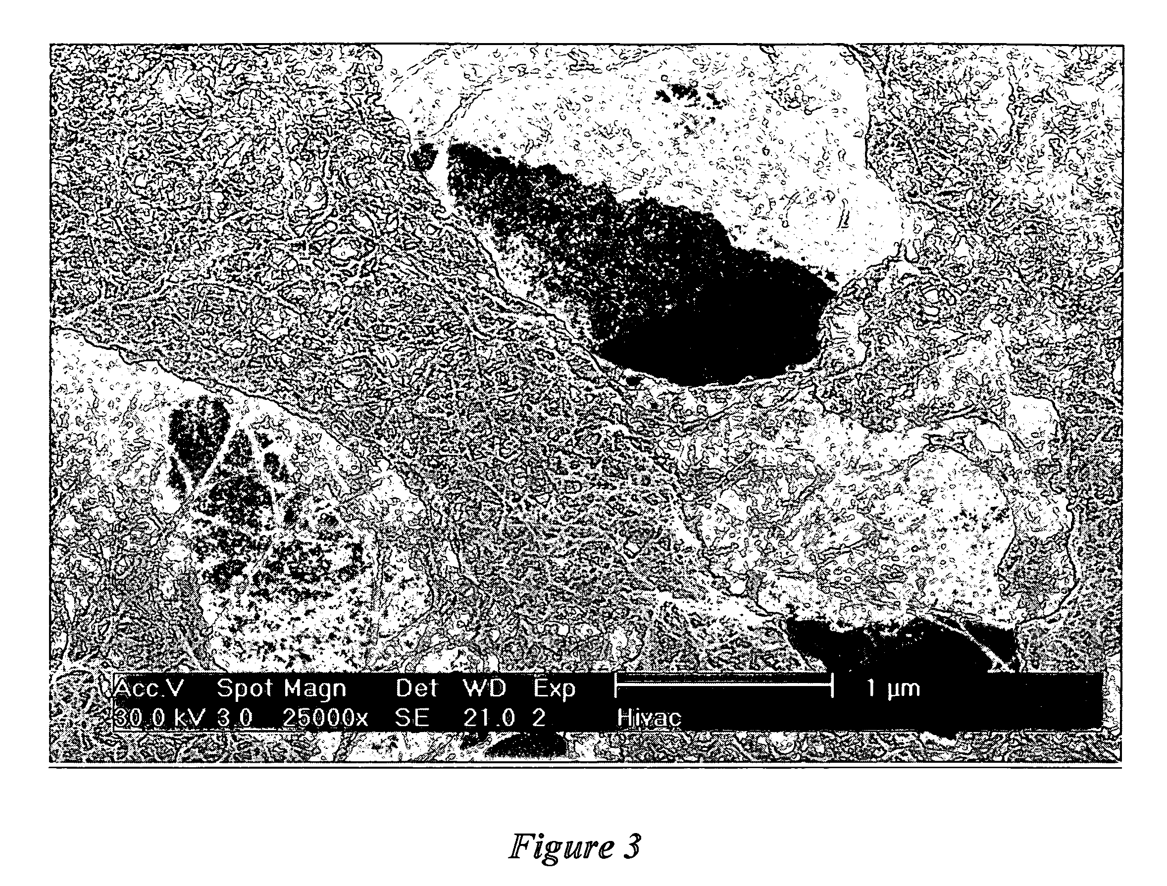
Image

Examples
example 1
[0099] 0.40 g iron (III) nitrate nonahydrate, (Fe(NO3)3·9H2O) (Mol. Wt. 404.02), 0.0365 g ammonium heptamolybdate tetrahydrate ((NH4)6Mo7O24·4H2O), 10 g magnesium nitrate hexahydrate (Mg(NO3)2·6H2O), and 4 g anhydrous citric acid were dissolved in a 500-ml beaker with 10 mls deionized water. As soon as a clear solution was formed, the beaker was placed in a high temperature furnace preheated at 650° C. A sudden drop in furnace temperature was observed. In a few minutes the solution foamed and a large quantity of light yellow fluffy flakes filled the beaker. The furnace temperature was reduced to 550° C. and the catalyst was held at 550° C. for 60 minutes. The catalyst was removed from the furnace and placed in a desiccator. With aid of a blender, the catalyst flakes were readily ground to fine flowing powder. The physical characteristics of the catalyst powder were small primary particle size (3). The chemical composition of the resulting catalyst was: 3.5 wt % Fe and 1.3 wt % Mo. I...
example 2
[0103] This example demonstrates the production of small-diameter carbon nanotubes using the catalyst of Example 1 treated with a sulfur-containing compound.
[0104] 1 g catalyst, as prepared in Example 1, was placed in a fluidized bed reactor. The reactor was purged with argon gas (flow rate: 150 sccm) and the temperature was increased at a rate of 20° C. / min to 500° C. At 500° C., thiophene (C4H4S, Acros) was introduced to the catalyst by passing the argon through thiophene held at room temperature for 10 minutes. After thiophene treatment, the reactor temperature was raised to 850° C. under an argon purge. At 850° C., the argon was turned off and methane (CH4. Matheson) was introduced for 10 minutes to grow nanotubes. After the 10 minutes of growth reaction, the methane was turned off and argon was turned on. The reactor was cooled to room temperature under an argon purge. The resulting material retrieved from the reactor was dark black powder. The growth of SWNT, as measured by T...
example 3
[0108] This example demonstrates the growth of small-diameter carbon nanotubes using a catalyst with a different iron and molybdenum composition. 1.1 g iron nitrate nonahydrate (Fe(NO3)3·9H2O), 0.028 g ammonium heptamolybdate tetrahydrate ((NH4)6Mo7O24·4H2O), 20 g magnesium nitrate hexahydrate (Mg(NO3)2·6H2O). and 6 g anhydrous citric acid were dissolved in 20 ml deionized water in a 500-ml beaker. The rest of the preparation procedure was identical to Example 1. The catalyst metal composition of the resulting catalyst was 4.8 wt % Fe and 0.48 wt % Mo. The physical properties were similar those of the catalyst in Example 1.
[0109] 1 g catalyst was placed in a fixed fluidized bed reactor. The reactor was first purged with argon gas (flow rate: 150 sccm) and the temperature was increased at a rate of 20° C. / min to 850° C. At 850° C., the argon was turned off and methane (CH4) was turned on for 10 minutes and then turned off. The reactor was cooled to room temperature under an argon pu...
PUM
| Property | Measurement | Unit |
|---|---|---|
| outer diameter | aaaaa | aaaaa |
| outer diameter | aaaaa | aaaaa |
| density | aaaaa | aaaaa |
Abstract
Description
Claims
Application Information