Optical information recording medium, reproducting method using the same, and optical information processing device

a technology of optical information and recording medium, applied in the field of optical information recording medium, can solve the problems of insufficient reliability of information reproduction, na limitation, and inability to shorten the wavelength of the light source, so as to achieve effective change of complex refractive index, enhance the effect of light absorption in the optical multiple interference film, and effectively change the complex refractive index

Inactive Publication Date: 2005-01-13
SHARP KK
View PDF20 Cites 30 Cited by
  • Summary
  • Abstract
  • Description
  • Claims
  • Application Information

AI Technical Summary

Benefits of technology

Since the single optical multiple interference film is included in the aforesaid at least one thin film of the thin film section, the optical multiple interference occurs virtually due to the repeating reflections on the light-incident surface and the opposing surface of the optical multiple interference film. Thus, the effect of light absorption in the optical multiple interference film is enhanced, so that the degree of the change of the complex refractive index is effectively increased. In particular, when the complex refractive index of the optical multiple interference film changes in accordance with the temperature change, the temperature change due to the light absorption in the optical multiple interference film is great, making it possible to effectively change the complex refractive index.
Moreover, comparing to a case that a transparent film which repeatedly reflects light is provided in addition to the optical multiple interference film, the thickness of the optical multiple interference film can be further thickened. Thus, it is possible to further enhance the change of the reflectance in the thin film section, by increasing the thickness of the optical multiple interference film.
Moreover, comparing to a case that a transparent film which repeatedly reflects light is provided in addition to the optical multiple interference film, the state of the optical multiple interference can be mainly controlled only by adjusting the thickness and refractive index of the optical multiple interference film. This makes it easy to manufacture the optical information recording medium, and decrease the manufacturing costs thereof.
For these reasons, the control of the state of optical interference and the manufacture of the medium become easy. Furthermore, the efficiency of the use of light is improved, so that the sensitivity to the optical power is improved.

Problems solved by technology

However, it is considered that the wavelength λ of the light source cannot be shortened beyond the wavelength of ultraviolet light due to the adsorption by an optical element and the limitation of sensitivity characteristics of a detector, and the NA is also limited by the maximum allowable tilt of the medium.
Adopting an organic material as a mask layer, a medium in accordance with the methods (1) and (2) using organic dye and photochromic tend to be degraded by heat and can be read only about not more than 10,000 times, so as not to have sufficient reliability for information reproduction and thus have not been in practical use.
Furthermore, due to the degradation by heat, these methods (1) and (2) cannot be adopted to produce rewritable disks.
When the extinction coefficient k is such a large value, it is impossible to effectively increase the range of the reflectance change in the film stack.
Such a semitransparent inorganic super-resolution film absorbs light in the course of repeating the optical multiple interference, and hence one cannot fully exploit the optical multiple interference.
For this reason, it is impossible to fully exploit the multiple interference, and this should be problematic in terms of the efficiency of the use of light.
However, when the inorganic super-resolution film is semitransparent, light cannot pass through a thickened inorganic super-resolution film, and hence it is impractical to increase the thickness of the inorganic super-resolution film.
The reduction is particularly significant in short wavelengths, and this hampers the use of the multiple interference and efficient use of light.
In particular, since the efficiency of the use of light in the film stack is reduced when the inorganic super-resolution film is semitransparent, it is not possible to adopt a multi-layered recording section structure in which recording layers for recording information and recording surfaces recording information with irregularities thereon are deposited.
However, since the change of the complex refractive index is an inherent property of a material, this approach would make little improvements.
This decreases the efficiency of the use of light and gives rise to signal noise and failure in a servo.
For this reason, the interference film stack deteriorates the signal quality.
Furthermore, the refractive index of the film and the thickness of the film cannot be easily adjusted.
Thus, providing the interference film stack increases the number of manufacturing steps of the optical recording medium and increases the manufacturing costs thereof.

Method used


Image

  • Optical information recording medium, reproducting method using the same, and optical information processing device
  • Optical information recording medium, reproducting method using the same, and optical information processing device
  • Optical information recording medium, reproducting method using the same, and optical information processing device

Examples


example 1

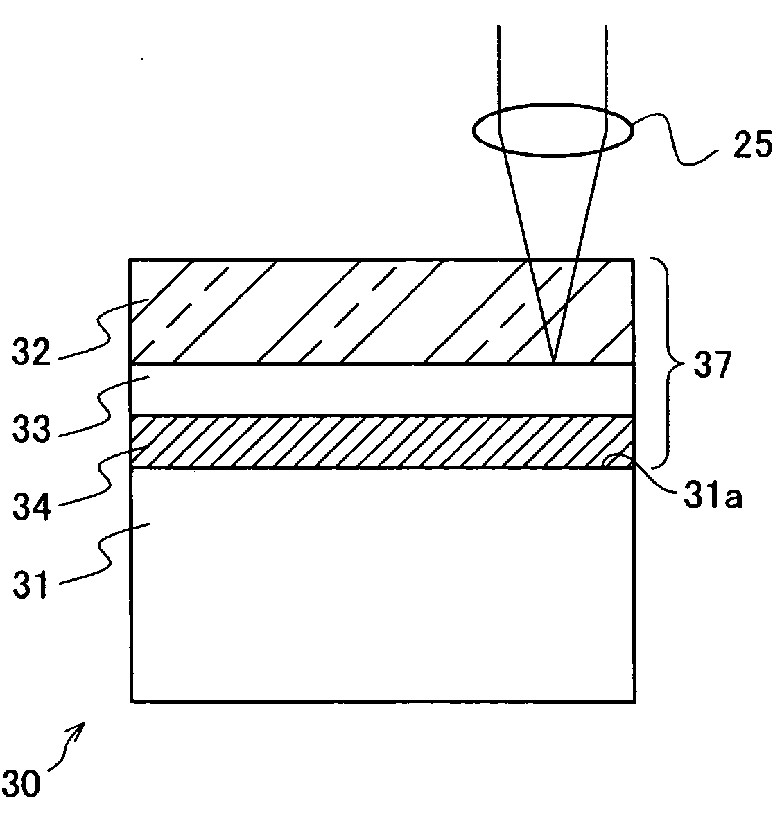
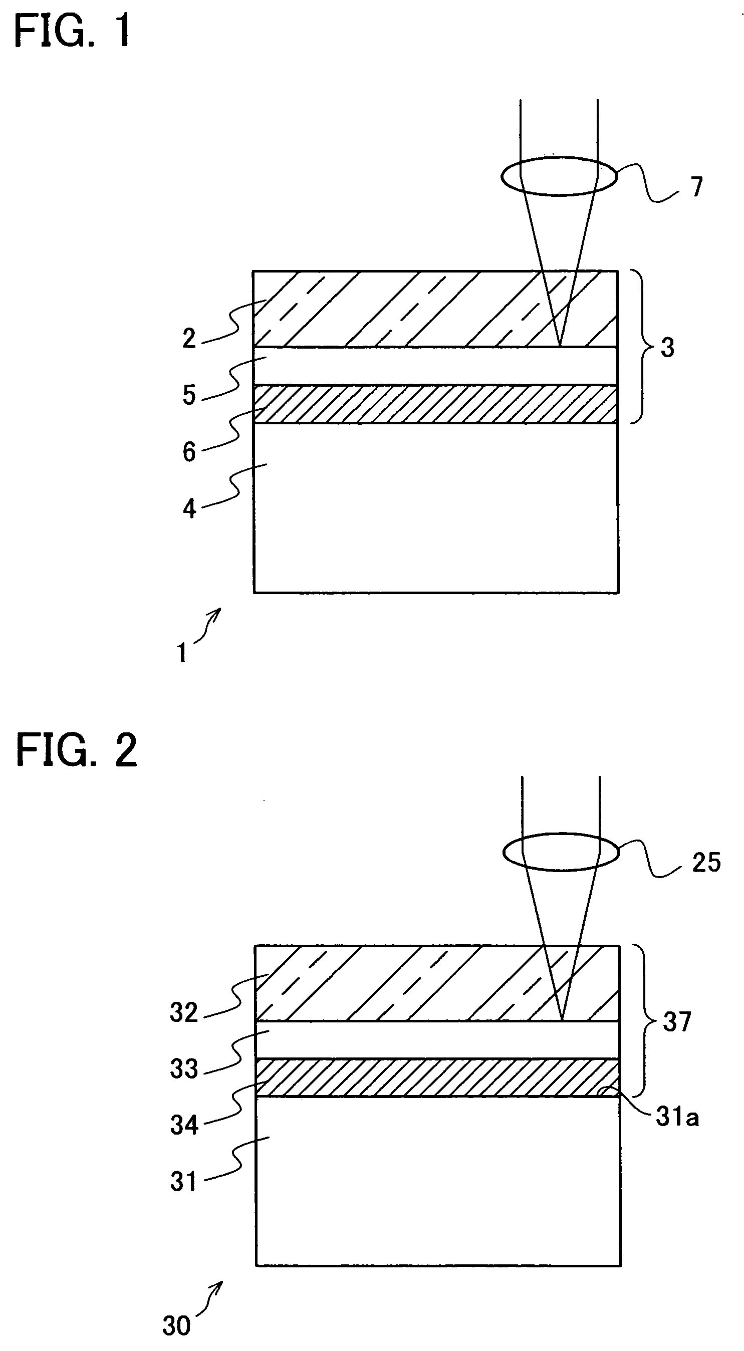
FIG. 2 is a cross section of an optical information recording medium 30 of Example 1 which is one of the examples of the present invention. This optical information recording medium 30 is a playback-only type. A substrate 31 is a polycarbonate substrate 12 cm in diameter and 1.1 mm thick. On one surface 31a of the substrate 31, information is recorded in advance in the form of phase pits. This surface 31a is the recording surface.

Next, on the surface 31a of the substrate 31, an Al film 30 nm thick is formed as a reflective film 34, by a magnetron sputtering method. On this reflective film 34, a Si film 50 nm thick is formed as a light-absorbing film 33, and a ZnO film 220 nm thick as a temperature-sensitive film 32 is further formed thereon. In this manner, a film stack (thin film section) 37 made up of, from the incident-light side, the temperature-sensitive film 32, the light-absorbing film 33, and the reflective film 34 is formed on the substrate 31.

As described above, the pr...

example 2

FIG. 7 is a cross section of an optical information recording medium 41 of Example 2, and this optical information recording medium 41 includes a two-layered film stack 38 in which a temperature-sensitive film 32 and a light-absorbing film 33 are deposited in this order from the incident-light side. Being identical with the optical information recording medium 30 of Example 1, the optical information recording medium 41 of Example 2 includes a substrate 31 made up of a polycarbonate plate which is 12 cm in diameter and 1.1 mm thick. On the recording surface 31a of the substrate 31, information is recorded in advance in the form of phase pits. On this recording surface 31a on which information has been recorded, an Si film 50 nm thick is formed as a light-absorbing film 33, by the magnetron sputtering identical with that in the optical information recording medium 30 of Example 1 and on the same sputtering conditions as those of the optical information recording medium 30 of Example ...

example 3

FIG. 8 is a cross section of an optical information recording medium 42 of Example 3, and this optical information recording medium 42 includes a three-layered film stack 39 in which a temperature-sensitive film 32, a light-absorbing film 33, and a transparent film 35 are deposited in this order from the incident-light side. Being identical with the optical information recording medium 30 of Example 1, the optical information recording medium 42 of Example 3 is arranged in the following manner: The transparent film 35 which is 20 nm thick and made up of an SiN film is formed on a recording surface 31a to which information is recorded, by the magnetron sputtering identical with that of Example 1. On this transparent film 35, a light-absorbing film 33 which is 50 nm thick and made up of an Si film is formed as in Example 1, and a temperature-sensitive film 32 which is 220 nm thick and made up of a ZnO film is further formed thereon. That is to say, in the optical information recording...


PUM

PropertyMeasurementUnit
wavelength distributionaaaaaaaaaa
wavelengthaaaaaaaaaa

Abstract

An optical information recording medium of the present invention includes a thin film section made up of one or more thin film, the thin film section being provided on a substrate. Thin films of the thin film section include a single optical multiple interference film which incites optical multiple interference in a thin film section, the optical multiple interference being incited by the change of complex refractive index in accordance with the intensity of incident light. Also, the composition and thickness of the optical multiple interference film are arranged in such a manner as to cause the wavelength distribution of the reflectance of the thin film section at room temperatures to have a minimum value within wavelengths of ±80 nm of the incident light for reproduction. With this, the design freedom of the optical multiple interference film which realizes super-resolution reproduction with a reduced effective reproduction spot is significantly increased.

Description

This Nonprovisional application claims priority under 35 U.S.C. §119(a) on Patent Application No. 2003 / 162882 filed in Japan on Jun. 6, 2003 and Patent Application No. 2004 / 153825 filed in Japan on May 24, 2004, the entire contents of which are hereby incorporated by reference. FIELD OF THE INVENTION The present invention relates to an optical information recording medium which can record / reproduce information or reproduce information using light, and more particularly to an optical information recording medium employing super-resolution medium technology which makes it possible to read recording marks that cannot be read with an optical resolving power determined by a diffraction-limited optical spot size, a reproduction method using the optical information recording medium, and an optical information processing device. BACKGROUND OF THE INVENTION The recent progress of informatization, information-communication, and multimedia technologies has created strong demands for high-de...

Claims


Application Information

Patent Timeline
Patent Type & Authority Applications(United States)
IPC IPC(8): G11B7/24G11B7/243G11B7/257
CPCB82Y10/00G11B7/24G11B7/257G11B7/2534G11B7/243Y10S430/146
Inventor MORI, GOYAMAMOTO, MASAKITAJIMA, HIDEHARUTAKAMORI, NOBUYUKI
Owner SHARP KK
Why Eureka
Try Eureka