Eureka AIR delivers breakthrough ideas for toughest innovation challenges, trusted by R&D personnel around the world.

Regenerative fuel cell technology

a fuel cell and regenerative technology, applied in the direction of battery/fuel cell control arrangement, secondary cell servicing/maintenance, cell components, etc., can solve the problems of increasing compression costs, reducing catalyst costs associated with fuel cell operation at higher pressure, and increasing costs of unreacted oxygen discharge from the fuel cell. , to achieve the effect of increasing the rate constant and being less expensiv

Inactive Publication Date: 2005-01-13
SUPPES GALEN J
View PDF3 Cites 114 Cited by
  • Summary
  • Abstract
  • Description
  • Claims
  • Application Information

AI Technical Summary

Benefits of technology

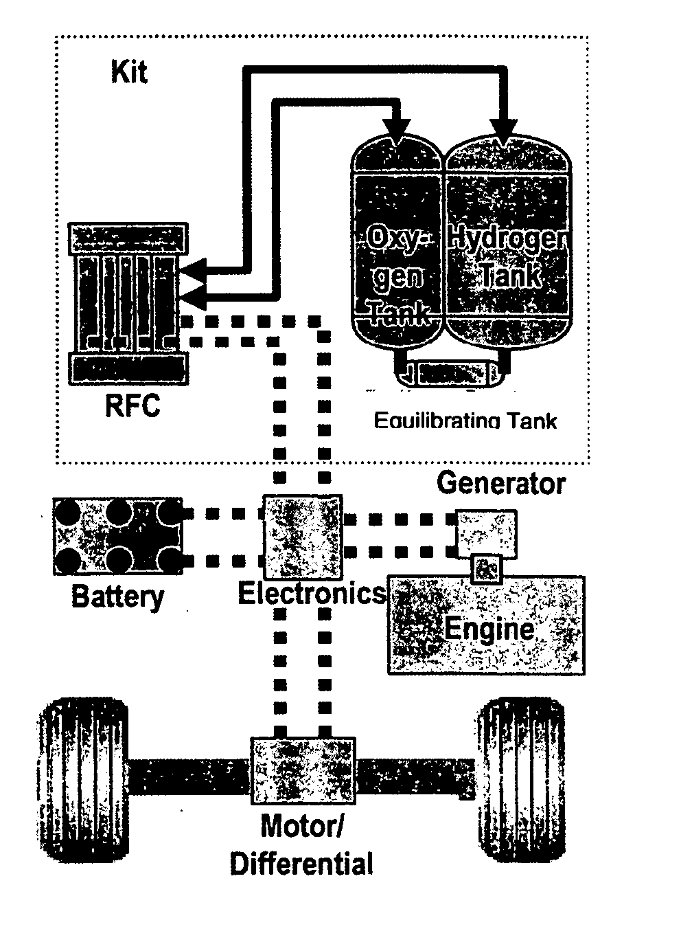
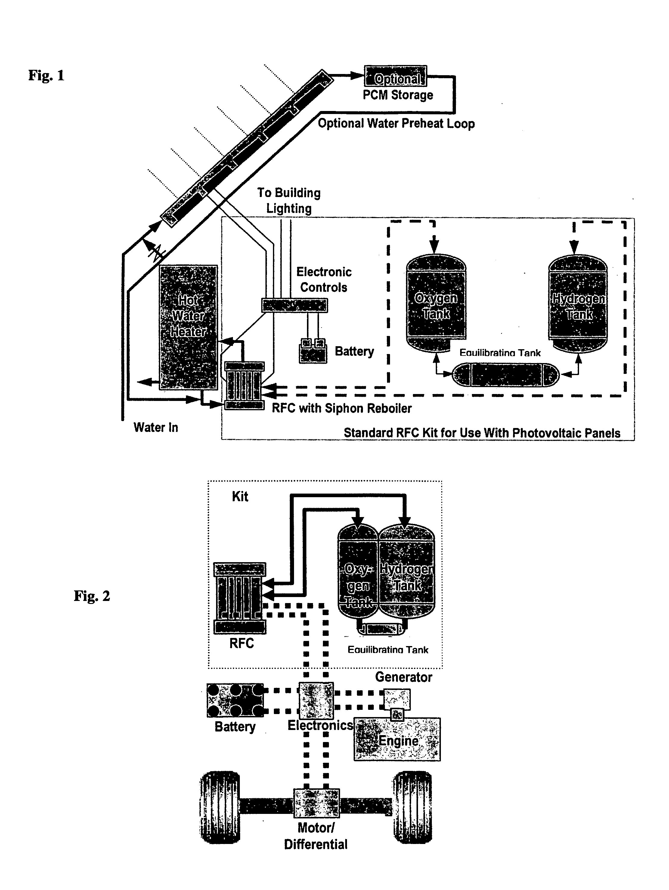
[0019] An alternative embodiment is a plug-in electric vehicle with a fuel cell battery charger that uses an engine battery, and fuel cell in combination to provide power to the vehicle. The engine provides backup power for longer distance travel. For shorter distances after recharging the battery and hydrogen / oxygen tanks, the fuel cell and battery work in combination to provide both range and power. The advantage is that a small fuel cell allows for high ranges without a large number of batteries while the batteries provide for high power output without a large fuel cell. The combination of the small fuel cell used as a battery charger and the batteries is less expensive than a system comprised of fuel cells alone or batteries alone.

Problems solved by technology

Especially when oxygen is compressed to high pressures, it is quite costly to discharge unreacted oxygen from the fuel cell.
In conventional approaches to fuel cell design, reduced catalyst costs associated with operating the fuel cell at higher pressures are diminished by increasing compression costs (for compressing oxygen or air and for compression hydrogen).
Furthermore, the static pressures of conventional fuel cell designs are limited by the pressures the membranes can contain.
The energy losses associated with air separation and compression of oxygen occur whether the oxygen is used immediately or stored.

Method used


Image

  • Regenerative fuel cell technology
  • Regenerative fuel cell technology
  • Regenerative fuel cell technology

Examples


Embodiment Construction

[0037] The Components of Fuel Cell Embodiments: In a fuel cell system that produces electrical power through electrochemical reactions of oxygen and a fuel, the fuel cell system includes at least one fuel cell stack. The fuel cell stack is enclosed in a high pressure containment such as a pressure vessel. The fuel cell system is comprised of at least: a fuel cell stack, an oxidant entrance and a fuel entrance, media (such as membranes or salt bridges) substantially permeable to the transport of ions through said media / membrane while being substantially impermeable to the transport of electrons, each single said medium having an anode side and a cathode side, cathodes contacting the cathode sides of the membranes, anodes contacting anode sides of the membranes, and a circuit connected to both the cathode and anode capable of conducting electrons but substantially impermeable to the transport of ions. Both the cathode and anode have catalysts that promote reactions involving the relea...


PUM

PropertyMeasurementUnit
poweraaaaaaaaaa
poweraaaaaaaaaa
poweraaaaaaaaaa

Abstract

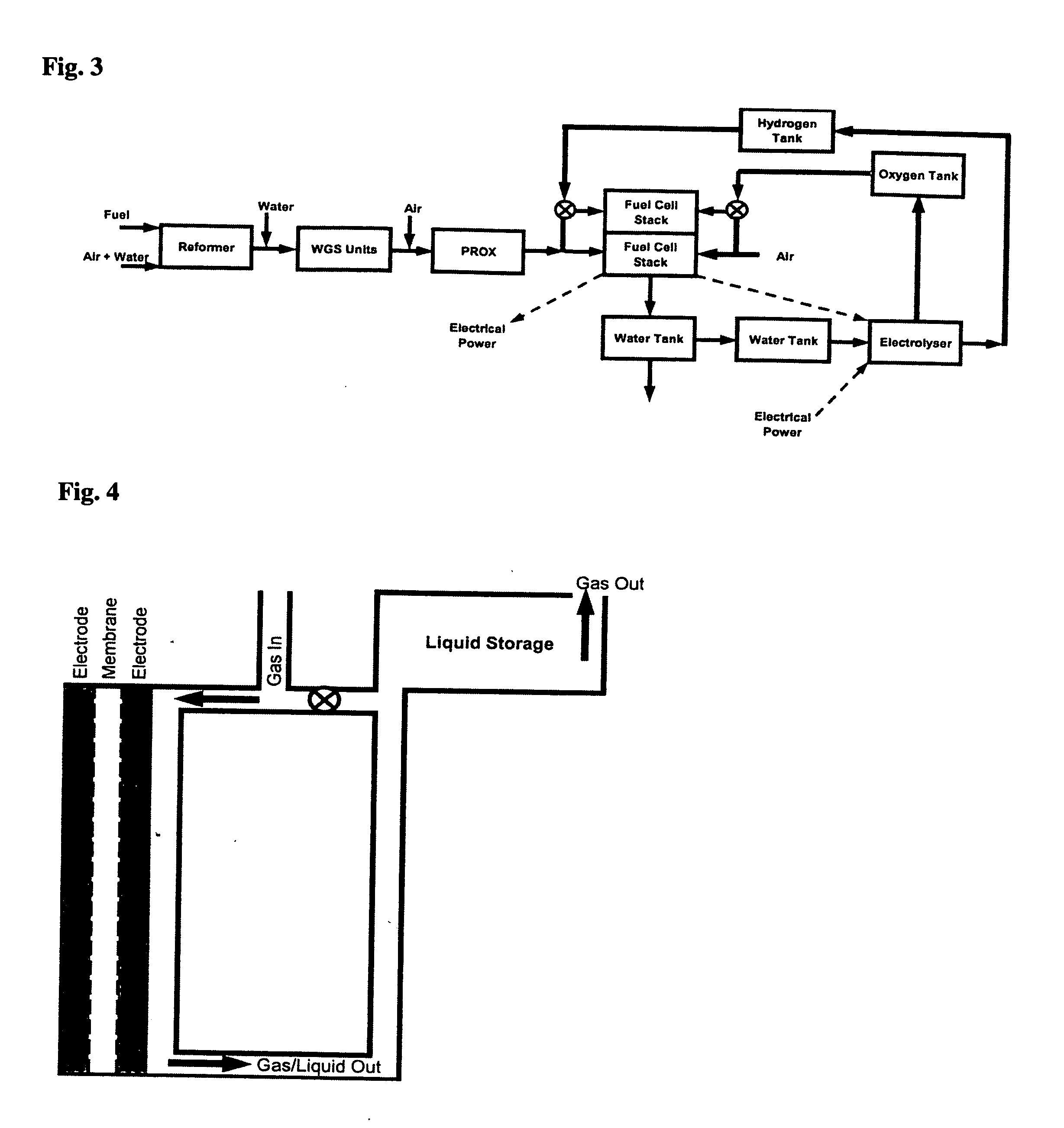
For a mobile fuel cell system a narrow-gap modular approach allows reforming to be performed in the same architecture as the fuel cell. A regenerative fuel cell operates much like a battery using electrical power to produce hydrogen and oxygen. The preferred mode of using the regenerative fuel cell is as a battery charger since this application is able to use a much smaller fuel cell than is required to power the vehicle. A novel equilibrating tank between the electrolysis oxygen and hydrogen tanks allows pressurized oxygen and hydrogen to be used without mechanical compression equipment.

Description

CROSS REFERENCE TO RELATED APPLICATIONS [0001] A This application claims priority of the following U.S. Provisional Patent Applications: Ser. No. 60 / 486280, filed Jul. 11, 2003; Ser. No. 60 / 519870, filed Nov. 13, 2004, and Ser. No. 60 / 541178, filed Feb. 2, 2004.BACKGROUND OF THE INVENTION [0002] 1. Field of Invention [0003] This invention is in the area of fuel cell technology. Specifically, the invention is on a high pressure regenerative fuel cell system that operates like a battery and the use of this regenerative fuel cell system in a plug-in hybrid electric vehicle. [0004] 2. Description of Prior Art [0005] Use of the fuel cell as a battery charger in a plug-in hybrid electric vehicle is a novel approach. No similar art was located. [0006] Patent application 20040074040 of J. J. Duffy et al. uses a high pressure electrolyzer and pressure equalization system. The differential pressure controls of the system of Duffy et al are not necessary with the embodiments of this invention....

Claims


Application Information

Patent Timeline
Patent Type & Authority Applications(United States)
IPC IPC(8): H01J7/34H01M8/04H01M8/18H01M10/46H01M16/00
CPCB60L11/1881H01M8/04089H01M8/0432H01M8/04701Y02T90/34H01M8/0494H01M8/186H01M16/006Y02E60/528H01M8/04753B60L58/30Y02E60/10Y02E60/50Y02T90/40
Inventor SUPPES, GALEN J.
Owner SUPPES GALEN J
Why Eureka
Eureka Blog
Learn More