[0011] An object of the present invention is to provide a novel and elegant combined engine for a single-stage spacecraft combining an air-
breathing engine utilizing the
oxygen present in the atmosphere as oxidizer with rocket engines to obtain thrust outside the atmosphere. However, in which mechanical alteration of shape for changing
over the air-breathing engine mode in accordance with flight speed is unnecessary and that makes it possible fluid-dynamically to obtain the same function as this mechanical alteration of shape.
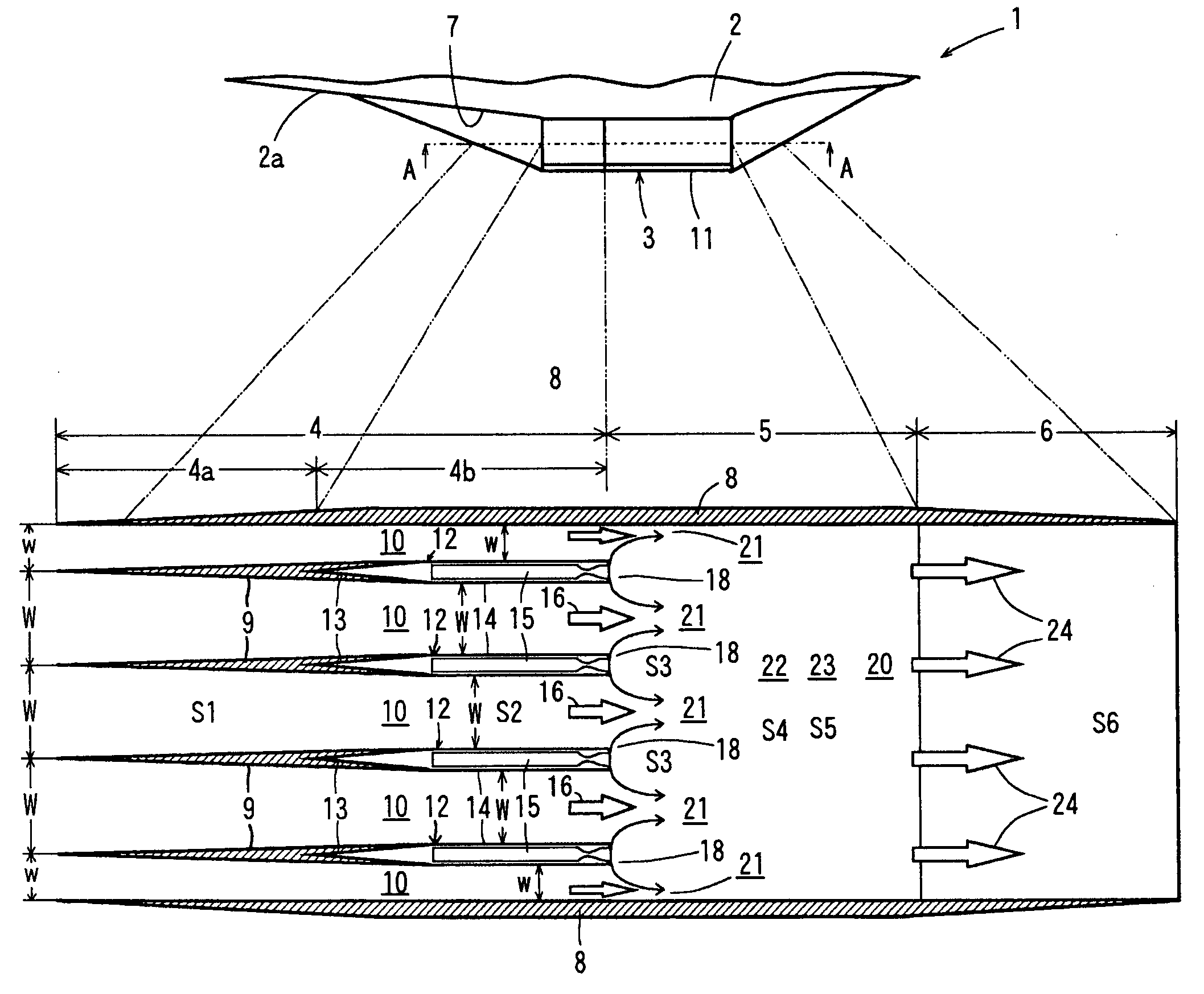
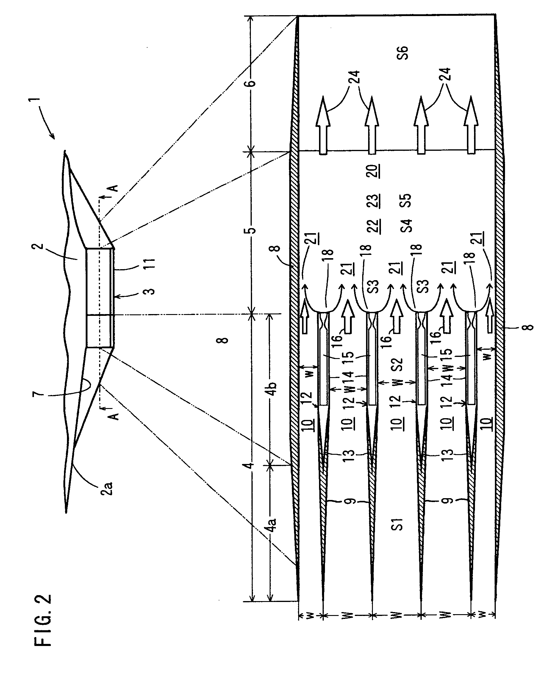
[0015] In this combined engine for a spacecraft, each flow rate of the
airflow may be controlled by varying the
air channel area of said
airflow immediately upstream of said mixing section by varying the shape of said rocket jets. Changing the shape of the rocket jets alter the
air channel areas of the airflows. Controlling the
rocket engine combustion pressure easily performs the change of the shape of the rocket jet. The entering airflows will be mixed with the fuel-rich rocket exhaust gases for combustion, i. e. air-breathing engine. The channel areas of the airflows become narrower as the widths of the rocket jets are increased. Controlling the rate of incoming air flowing into the
combustion chamber by means of the rocket jets (i.e. controlling the
combustion chamber pressure) is much easier than inlet
shape control by a variable structure. Thus, even though each passage wall
surface shape of the air introduction channel is fixed and invariant, this can play the role of an adaptable inlet that is automatically adapted to the main fluid dynamical elements of the air-
breathing cycle engine in the entire flight speed region. That is the channel areas of the airflows can be altered by means of the widths of the rocket jets, instead of using a variable-shape inlet.
[0016] In this combined engine for a spacecraft, by changing the shapes of the rocket jets, the air intake section can provide an
equivalent function to that of the variable-shape air intake section that is required in a
Brayton cycle engine in supersonic or ultra-supersonic flight. In the actual high supersonic
Brayton cycle engine, the air intake section (inlet) is made geometrically variable. The variable-shaped air intake section is required that presents different shapes depending on the flight Mach numbers during supersonic and ultra-supersonic flight. The combined engine for a single-stage spacecraft according to the present invention, an equivalent role to that of the variable-shaped air intake section can be performed by fluid dynamically
adaptation provided by the shapes of the jets. By varying the shapes of the rocket jets, this can be easily performed even though the air intake section is of geometrically fixed shape.
[0018] In order to secure the operation of the combined engine at ultra-supersonic flight speeds of flight such as beyond the
speed limit of the conventional
scramjet Mach number 12 or more, some methods are needed to acquire the required static pressure, i. e. supersonic diffuser. In this combined engine for a spacecraft comprising a jet diffuser as stated previously, the necessary combustion pressure is secured by the mixture mainly with the pressure of said rocket jet, in addition to an
equivalent function to the variable shape diffuser of said
rocket engine. In the flight Mach number region (9<M∞<12) that is believed to represent the limit for flight using a
Brayton cycle engine, the necessary combustion pressure is secured by mixing with the pressure of the rocket jets, in addition to the rise in static pressure produced by the jet diffuser, thereby making it possible to achieve flight of the spacecraft beyond the aforesaid flight limit.
[0021] In this combined engine for a single-stage spacecraft, the air / fuel flow
rate ratio in said mixing section can be controlled by altering the equivalent ratio of oxidizer and fuel in the combustion chambers of the rocket engines. When the rocket engines are operated under excess fuel condition, the air / fuel flow rate of the
mixed gas in the mixing section can be altered to be fuel-rich. That can be easily performed by changing the flow
rate ratio O / F of the oxidizer / fuel in the combustion chambers of the rocket engines.
[0022] In this combined engine for a single-stage spacecraft, the rocket jets may generate Mach disks upstream of the mixing section in a subsonic or supersonic flight speed region. A rise in pressure on the downstream side of the Mach disks can be produced by generation of the Mach disks by the injection into the mixing section. Specifically, in a Brayton cycle
jet engine, for low-speed flight such as subsonic flight or supersonic flight at lower Mach number than higher supersonic, it is required that the incoming
airflow should be compressed to raise the combustion pressure. With the present invention, the Mach disks (perpendicular
shock wave) generated upstream of the mixing section can achieve the same role as that of the required mechanical compressor of the
turbojet engine while adapting fluid-dynamically thereto. Also, the Mach disks (perpendicular
shock wave) generated by the rocket jets absorb fluctuations of static pressure generated in the downstream mixing section and combustion section. That so makes it possible to stabilize the air flow rate within the engine such that there are no effects on the flow of the upstream section, which is in a subsonic condition.

