
Apparatus and method for water treatment by a direct co-precipitation/filtration process

Inactive Publication Date: 2005-01-27
STEVENS INSTITUTE OF TECHNOLOGY
View PDF11 Cites 8 Cited by
  • Summary
  • Abstract
  • Description
  • Claims
  • Application Information

AI Technical Summary

Benefits of technology

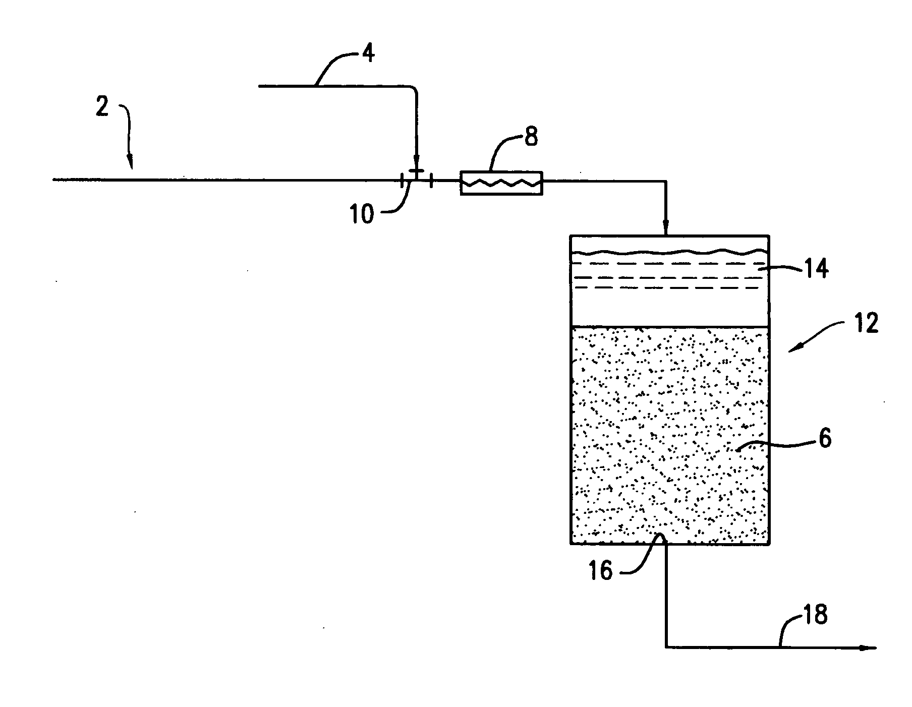
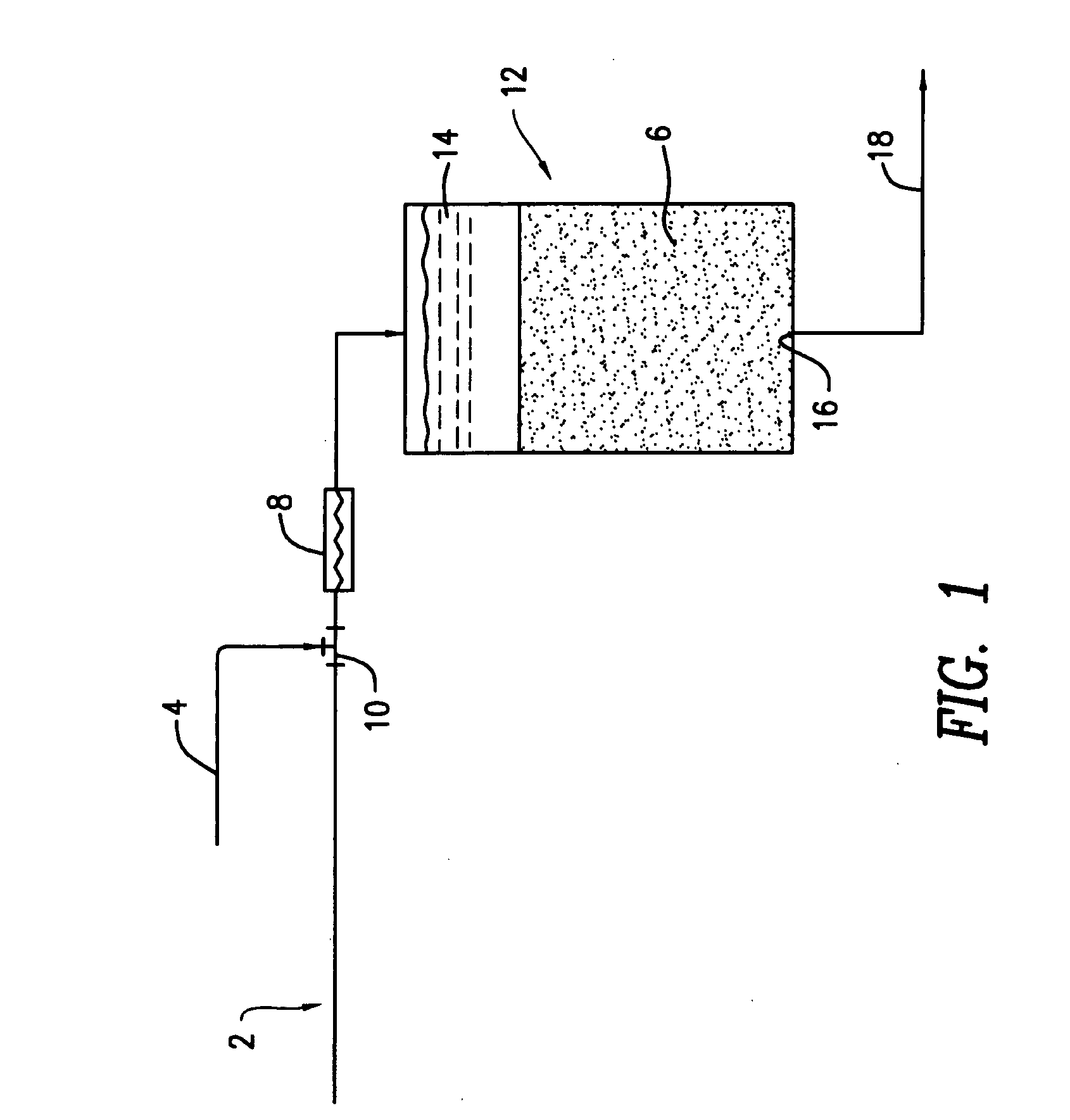
[0011] The present invention comprises an apparatus and method for removing dissolved contaminants from a dilute aqueous stream by a direct co-precipitation / filtration process. The apparatus includes a packed bed filter; an influent pipe for conveying a dilute aqueous stream to said packed bed filter; and an injection port for injection of a chemical solution into said influent line. The packed bed filter, influent pipe and injection port are arranged so that no substantial amount of particulate matter settles from the dilute aqueous stream between the injection port and the packed bed filter. This arrangement makes it unnecessary to provide a detention vessel for flocculation or sedimentation before the packed bed filter.
[0012] In the method, a hydrolysable metallic compound is added to the dilute aqueous stream, and the hydrolyzed metal co-precipitates with the contaminants. The resulting co-precipitate is filtered from the stream, preferably using a packed bed filter. Filtration and co-precipitation are performed concurrently in such a way that no substantial amount of particulate matter settles from the dilute aqueous stream before the start of said filtering step. Preferably, the dilute aqueous stream is filtered through a packed bed filter. It is also preferred that the addition of the hydrolysable metallic compound be performed less than seven minutes before the completion of the filtering step. Ferric salts are preferred as the hydrolysable metallic compound in the method of the invention, however, other metallic salts, such as aluminum sulfate, aluminum chloride, titanium sulfate, and titanium chloride. The method of the invention may be used effectively to remove dissolved contaminants that can be removed by conventional precipitation processes.

Problems solved by technology

This arrangement makes it unnecessary to provide a detention vessel for flocculation or sedimentation before the packed bed filter.

Method used


Image

  • Apparatus and method for water treatment by a direct co-precipitation/filtration process
  • Apparatus and method for water treatment by a direct co-precipitation/filtration process
  • Apparatus and method for water treatment by a direct co-precipitation/filtration process

Examples


example 1

Arsenic Removal by Direct Co-Precipitation Filtration with Iron

[0025] Bench-scale column filtration tests were performed to evaluate the effectiveness of the direct coprecipitation filtration process in removing dissolved arsenic (As(V)) from water when dissolved iron (Fe(III)) was used as a co-precipitant. The configuration of the bench-scale DCF system used for these tests was similar to that shown in FIG. 1, with a water pump for the influent 2 and an injection pump for the co-precipitant solution 4. An in-line mixer 8 was not included in the bench-scale DCF system. The sand filter column 12 had an inside diameter of 3.0 inches (7.6 cm) and was packed with approximately 20 inches (51 cm) of quartz sand having an effective diameter of 0.35-0.60 mm and a uniformity coefficient of 1.2-1.6 (Ricci Bros. Sand Co. Inc., Port Norris, N.J.) to form the filter bed 6.

[0026] The sand filter was operated at a constant filtration rate of 3 gal / min▬ft2, providing a detention time of about 2.5...

example 2

Effect of Iron Dosage on Effluent Arsenic Concentration

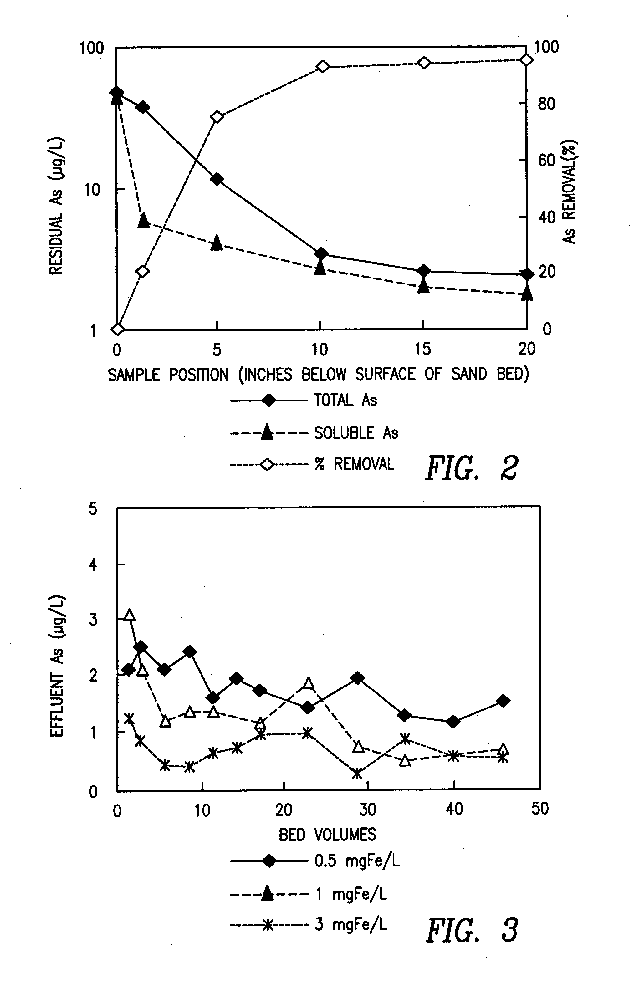
[0030] Bench-scale column filtration tests were performed to examine the effect of iron (Fe(III)) dosage on arsenic removal using the DCF test apparatus of Example 1. The tests were performed on an influent consisting of tap water spiked to a concentration of 16 μg As(V) / L. In each test, the influent was dosed to a selected concentration of iron upstream of the sand filter. Tests were run at dosages of 0.5, 1.0 and 3.0 mg Fe(III) / L. Samples were collected from the effluent stream 18 throughout each test and analyzed for arsenic. Referring to FIG. 3, an iron dosage of 0.5 mg Fe(III) / L resulted in an effluent arsenic concentration of approximately 1.8 μg As(V) / L. At an iron dosage of 1 mg Fe(III) / L, the effluent arsenic concentration was reduced to about 1 μg As(V) / L. Increasing the iron dosage to 3 mg Fe(III) / L did not result in a commensurate decrease in effluent arsenic concentration below 1 μg As(V) / L.

example 3

Effect of Influent Arsenic Concentration on Arsenic Removal

[0031] Bench-scale column filtration tests were performed to evaluate the effect of the influent arsenic (As(V)) concentration on removal of arsenic by the DCF test apparatus of Example 1. Tests were performed on tap water samples spiked to arsenic concentrations of 16, 50, 90 and 180 μg As(V) / L, respectively. A separate test was performed using contaminated groundwater having an arsenic concentration of 70 μg As(V) / L. The influent streams were dosed to an iron concentration of 1 mg Fe(III) / L in each test.

[0032] Referring to FIG. 4, the DCF process reduced the effluent arsenic concentrations to about 1 μg As(V) / L in the 16 and 50 μg As(V) / L samples after less than 10 bed volumes of influent were passed through the sand filter. The effluent arsenic concentration increased to about 3 μg As(V) / L when the influent arsenic concentration was increased to 90 μg As(V) / L. A larger volume of influent, about 20 bed volumes, was treat...


PUM


Abstract

Dissolved inorganic contaminants are removed from a dilute aqueous stream by adding a hydrolysable metal compound to the aqueous stream, co-precipitating a hydrolyzed metal compound with the inorganic contaminants, and, concurrently with the co-precipitation step, filtering the co-precipitate from the dilute aqueous stream using a packed bed filter. The process may be carried out so that the metal oxide co-precipitate forms within the packed bed. Dissolved contaminants, particularly arsenic compounds, are removed more efficiently than by conventional co-precipitation / filtration processes. An apparatus for carrying out the process provides for injection of the hydrolysable metal compound into the dilute aqueous stream immediately upstream of the packed bed filter, without an intervening flocculation or sedimentation vessel, thereby providing an effective contaminant removal system that requires a smaller footprint and lower capital cost than conventional water treatment systems.

Description

CROSS-REFERENCE TO RELATED APPLICATIONS [0001] This application is a continuation-in-part of U.S. patent application Ser. No. 10 / 049,107, filed on Jul. 1, 2002, which is a national stage application under 35 U.S.C. § 371 of International Application No. PCT / US00 / 17693, filed on Jun. 28, 2000, which claims the benefit of U.S. Provisional Patent Application No. 60 / 147,708, filed on Aug. 6, 1999.FIELD OF INVENTION [0002] The present invention relates to apparatus and methods for removing dissolved contaminants from aqueous streams. More particularly, the present invention relates to methods of removing dissolved inorganic contaminants from aqueous streams by co-precipitation and filtration of metal oxides. BACKGROUND OF INVENTION [0003] Wastewater and natural waters (e.g., surface water or groundwater) may contain a variety of dissolved inorganic substances from natural and anthropogenic sources. Regulatory limits have been set for a number of these substances in drinking water and for...

Claims


Application Information

Patent Timeline
IPC IPC(8): C02F1/34C02F1/52C02F1/70C02F1/72C02F1/76C02F1/78
CPCC02F1/34C02F1/5236C02F1/705C02F1/722C22B3/46C02F1/78C02F2101/20C22B3/22C02F1/76Y02P10/20
Inventor MENG, XIAOGUANGKORFIATIS, GEORGE P.
Owner STEVENS INSTITUTE OF TECHNOLOGY
Learn More