
Laser and environmental monitoring system

a technology of environmental monitoring and laser, which is applied in the field of monitoring systems, can solve the problems of unrealistically high electrical energy consumption, commercial impracticality, and inability to commercially practical femtosecond lasers until recently, and achieves the effects of minimizing the spread of the agent, fast and real-time analysis and feedback, and cost-effectiveness

Active Publication Date: 2005-01-27
BOARD OF TRUSTEES OPERATING MICHIGAN STATE UNIV
View PDF99 Cites 69 Cited by
  • Summary
  • Abstract
  • Description
  • Claims
  • Application Information

AI Technical Summary

Problems solved by technology

Commercially practical femtosecond lasers have been unavailable until recently.
For example, lasers which can generate 10 femtosecond or less laser pulse durations have traditionally been extremely expensive, required unrealistically high electrical energy consumption (for extensive cooling, by way of example) and depended on laser dyes that had to be replenished every month thereby leading to commercial impracticality.
Ultrashort pulses are prone to suffer phase distortions as they propagate through or reflect from optics because of their broad bandwidth.
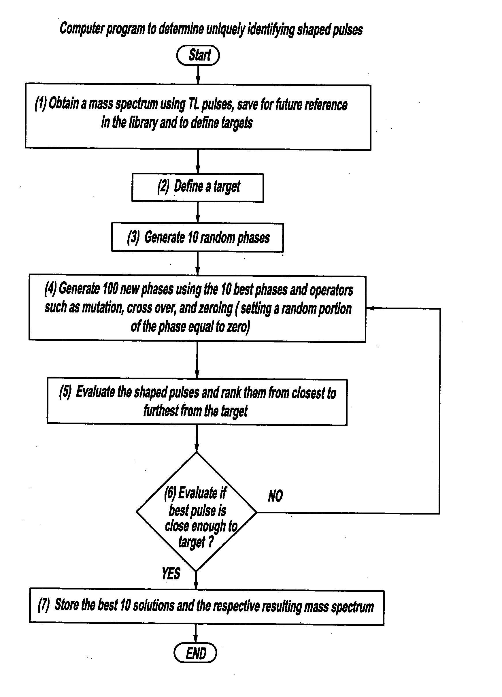
These shaped pulses require a very large data set and in many cases, complex learning calculations for determining the pulse shaping characteristics for a particular application.
Since the variation shape of the possible pulse shapes is huge, scanning the entire parameter space is impossible and as such the optimized pulse shape could not have been predicted by theory.
This dataset is extremely large, therefore, while in principle, the field exists to achieve the desired photonic transformation or excitation, finding it is a great challenge.
Conventional devices are only designed for use to detect a single known agent or are inaccurate.

Method used


Image

  • Laser and environmental monitoring system
  • Laser and environmental monitoring system
  • Laser and environmental monitoring system

Examples


Embodiment Construction

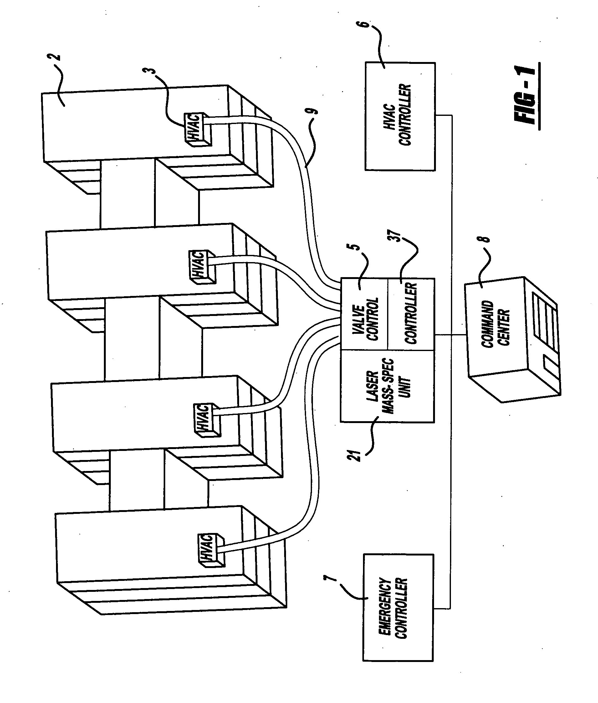
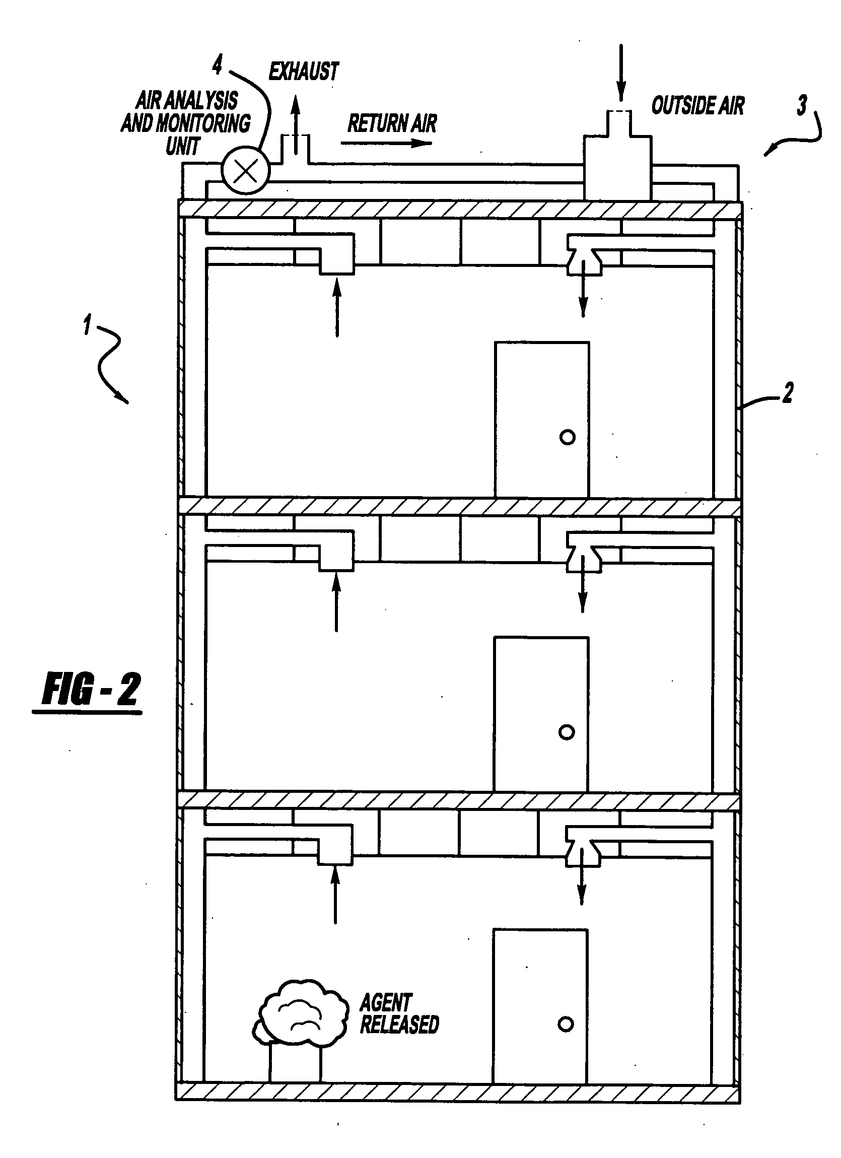
A laser and environmental monitoring system 1 is provided to monitor airborne chemical and biological agents in the desired environmental specimen or target area. This unit, because of its sensitivity, can be used to sense smoke from a fire. Referring to FIG. 1, a first preferred embodiment system 1 of the present invention includes a multi-story building 2, having a plurality of wings with interconnecting hallways, with each wing having separate ventilating systems, such as heating / ventilating / air conditioning climate control units (hereinafter “HVAC” units) 3. A laser and detection apparatus 21 is housed in a self-contained unit 4 with inlet valve controls 5. Furthermore, an HVAC control unit 6, a fire door / alarm / sprinkler emergency control unit 7 and a remote command center 8, such as a public safety or fire department 8, are also provided. Laser and detection apparatus 21 includes a femtosecond laser, pulse shaping optics, a mass spectrometer and a computer controller 37 as will...


PUM


Abstract

A laser and monitoring system is provided. In another aspect of the present invention, the system includes a laser, pulse shaper and detection device. A further aspect of the present invention employs a femtosecond laser and binary pulse shaping (BPS). Still another aspect of the present invention uses a laser beam pulse, a pulse shaper and a SHG crystal. In yet another aspect of the present invention, a multiphoton intrapulse interference phase scan (hereinafter “MIIPS”) method is used to characterize the spectral phase of femtosecond laser pulses and to correct them. A further aspect of the system of the present invention is employed to monitor environmental chemicals and biological agents, including toxins, explosives, and diseases.

Description

BACKGROUND The present invention generally relates to a monitoring system and more particularly to a laser and environmental monitoring system. Conventionally, laser desorption mass spectrometry has been used with a fixed laser beam pulse shape and computers for simple chemical analysis processes on purified molecules. The laser beam pulse shape was not considered an important parameter and was not modified; whatever fixed shape was set by the manufacturer for the ultraviolet laser was used in the tests. The general concept of typically laser selective ion formation from molecules in a molecular beam is disclosed in the following publication: Assion et al., “Control of Chemical Reactions by Feedback-Optimized Phase-Shaped Femtosecond Laser Pulses,”Science, Vol. 282, page 919 (Oct. 30, 1998). The pulse shaping process with a learning algorithm is disclosed in Judson et al., “Teaching Lasers to Control Molecules,”Physical Review Letters, Vol. 68, No. 10, page 1500 (Mar. 9, 1992). It...

Claims


Application Information

Patent Timeline
Patent Type & Authority Applications(United States)
IPC IPC(8): G01B9/02H01J49/16H01S3/00
CPCH01J49/162H01J49/164G01B9/02014G01B9/02091H01S3/0057
Inventor DANTUS, MARCOSLOZOVOY, VADIM V.COMSTOCK, MATTHEW
Owner BOARD OF TRUSTEES OPERATING MICHIGAN STATE UNIV
Learn More