
Apparatus and method for reactive sputtering deposition

Inactive Publication Date: 2005-02-10
KOREA ELECTROTECH RES INST
View PDF10 Cites 15 Cited by
  • Summary
  • Abstract
  • Description
  • Claims
  • Application Information

AI Technical Summary

Benefits of technology

[0011] It is another object of the present invention to provide a reactive sputtering deposition method enabling deposition of a metal oxide thin film on a substrate at a high rate by reactive sputtering.
[0014] It is another object of the present invention to provide a reactive sputtering deposition apparatus wherein a reactive gas is injected in the vicinity of a substrate and a sputtering gas is injected in the vicinity of a metal target, thereby accelerating oxidation of a metal target material to be deposited on the substrate and preventing oxidation of the metal target.
[0016] In order to accomplish the above objects of the present invention, there is provided a reactive sputtering deposition apparatus, comprising: a deposition chamber for creating an inner process atmosphere of the apparatus; a target including a metal material to be deposited; a substrate on which a reaction product of the metal material separated from the target with a reactive gas is deposited; and a partition plate dividing the deposition chamber into a reaction chamber at the side of the substrate and a sputtering chamber at the side of the target and provided between the target and the substrate, wherein an opening is formed through a central portion of the partition plate to allow the metal material separated from the target to reach the substrate. According to the apparatus of the present invention, the transfer of the reactive gas to the metal target is minimized and thus the oxidation of the metal target is prevented, thereby enabling deposition of a metal oxide thin film on the substrate at a high rate.
[0017] According to one embodiment of the apparatus of the present invention, the reactive sputtering deposition apparatus further comprises an exhaust port adapted to create a vacuum atmosphere, the exhaust vent being arranged at the reaction chamber to face a back surface of the substrate. The sputtering chamber is preferably arranged beneath the reaction chamber. In addition, the reactive sputtering deposition apparatus may further comprise a reactive gas supply tube for supplying a reactive gas to the reaction chamber so as to form a metal oxide film on the substrate through a reaction of the reactive gas with the metal material, the reactive gas supply tube being arranged at the reaction chamber. The reactive gas supply tube is preferably arranged toward the substrate in a direction opposite to the target. The reactive sputtering deposition apparatus may further comprise a reactive gas reservoir may be arranged at the substrate side of the reactive gas supply tube wherein a slot having a relatively large length with respect to its width is formed at the reactive gas reservoir along a length direction of the substrate, and the reactive gas is temporarily stored in the reactive gas reservoir before being injected into the substrate so as to retain a high energy. According to the apparatus of the present invention, the transfer of the reactive gas to the target is prevented, thus reducing oxidation of the target. The reactive gas used herein is oxygen, water vapor, hydrogen and a mixed gas thereof.
[0018] According to another embodiment of the apparatus of the present invention, the reactive sputtering deposition apparatus further comprises a cover surrounding the target material of the target and a sputtering gas supply tube for injecting a sputtering gas between the target material and the cover. The sputtering gas used herein is an inert gas, a reducing gas or a mixed gas thereof. The reducing gas is preferably hydrogen gas. The use of the sputtering gas prevents oxidation of the target material.
[0020] In accordance with another aspect of the present invention, there is provided a method for depositing a metal oxide on a substrate in a deposition chamber of a sputtering apparatus comprising the steps of: maintaining the deposition chamber in a state of being divided into a reaction chamber and a sputtering chamber; placing a substrate and a target in the reaction chamber and the sputtering chamber, respectively; keeping the atmosphere of the reaction chamber different from that of the sputtering chamber; reacting a metal material separated from the target in the sputtering chamber with a reactive gas present in the reaction chamber; and depositing the reaction product on the substrate. According to the method of the present invention, the transfer of the reactive gas to the metal target is minimized and thus the oxidation of the metal target is prevented, thereby enabling deposition of a metal oxide thin film on the substrate at a high rate.

Problems solved by technology
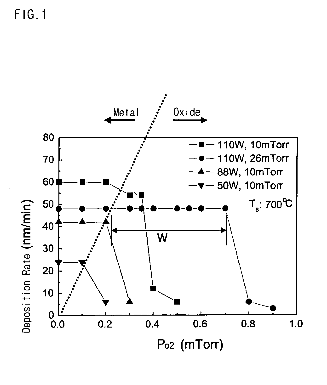
However, since the former type has a problem of low deposition rate, it is not suitable for practical application.
When the partial pressure of oxygen is too low, the metal material to be deposited on a substrate cannot be sufficiently oxidized to form a thin film having a desired phase.
Meanwhile, when the partial pressure of oxygen is too high, oxidation takes place on a target surface, causing low deposition rate.
Specifically, when the partial pressure of oxygen is too low, a metal material of a thin film to be deposited is not sufficiently oxidized and thus the metal material itself is deposited on a substrate.
On the other hand, when the partial pressure of oxygen is too high, a target is easily oxidized and thus the deposition rate tends to decrease sharply.

Method used


Image

  • Apparatus and method for reactive sputtering deposition
  • Apparatus and method for reactive sputtering deposition
  • Apparatus and method for reactive sputtering deposition

Examples


Embodiment Construction

[0035] A reactive sputtering deposition apparatus and a method for depositing a metal oxide according to preferred embodiments of the present invention will now be described in more detail with reference to the accompanying drawings. However, these embodiments are given for the purpose of illustration and are not to be construed as limiting the scope of the invention.

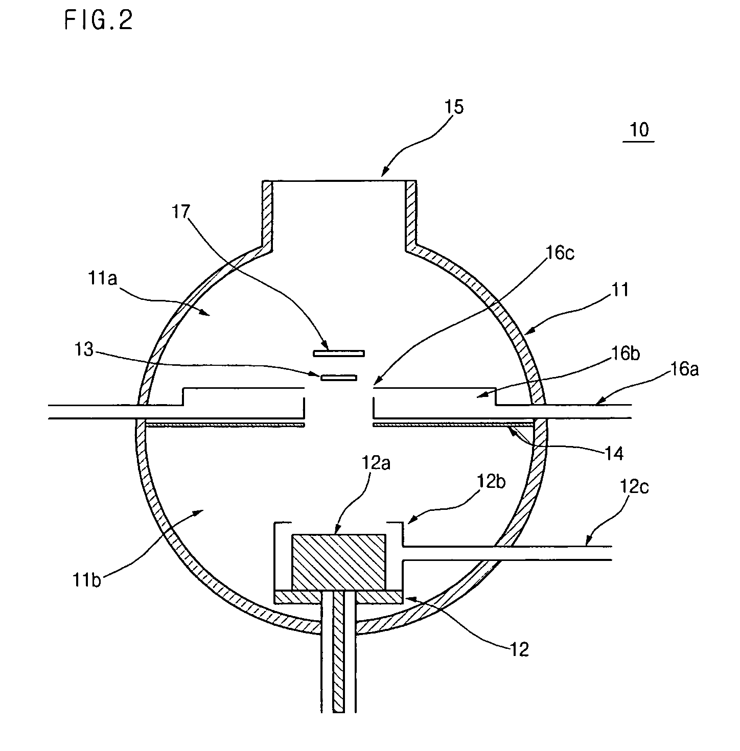
[0036]FIG. 2 is a cross-sectional view schematically showing a reactive sputtering deposition apparatus according to the present invention.

[0037] As shown in FIG. 2, the reactive sputtering deposition apparatus 10 of the present invention comprises a deposition chamber 11 for creating an inner process atmosphere of the apparatus 10, a target 12 including a metal target material to be deposited, a substrate 13 on which a reaction product of the metal material separated from the target 12 with a reactive gas is deposited, a partition plate 14 dividing the deposition chamber 11 into a reaction chamber 11a at the side of ...


PUM

PropertyMeasurementUnit
Lengthaaaaaaaaaa
Widthaaaaaaaaaa

Abstract

Disclosed herein is a reactive sputtering deposition apparatus in which a partition plate is provided between a sputtering target and a substrate. The reactive sputtering deposition apparatus comprises a deposition chamber for creating an inner process atmosphere of the apparatus, a target including a metal material to be deposited, a substrate on which a reaction product of the metal material separated from the target with a reactive gas is deposited, and a partition plate dividing the deposition chamber into a reaction chamber at the side of the substrate and a sputtering chamber at the side of the target and provided between the target and the substrate, wherein an opening is formed through a central portion of the partition plate to allow the metal material separated from the target to reach the substrate. According to the reactive sputtering deposition apparatus, the transfer of the reactive gas to the metal target is minimized and thus the oxidation of the metal target is prevented, thereby enabling deposition of a metal oxide thin film on the substrate at a high rate. Further disclosed is a reactive sputtering deposition method using the apparatus.

Description

BACKGROUND OF THE INVENTION [0001] 1. Field of the Invention [0002] The present invention relates to an apparatus and a method for reactive sputtering deposition. More particularly, the present invention relates to a reactive sputtering deposition apparatus in which a partition plate is provided between a sputtering target and a substrate, thereby enabling deposition of a metal oxide on the substrate at a high rate, and a reactive sputtering deposition method using the apparatus. [0003] 2. Description of the Related Art [0004] Chemical vapor deposition (CVD), sputtering deposition, molecular beam epitaxial (MBE) deposition and E-beam deposition methods have been used to deposit metal oxide thin films on substrates. Among these deposition methods, the sputtering deposition method is one wherein a metal material separated from a metal target by using an argon gas plasma, etc., is deposited on a substrate. [0005] Depending on the constituent materials of a target, deposition methods fo...

Claims


Application Information

Patent Timeline
IPC IPC(8): C23C14/00C23C14/08C23C14/34C23C14/32
CPCC23C14/0047C23C14/08C23C14/0068
Inventor PARK, CHANYOUM, DO-JUNKIM, HO-SUPCHUNG, KOOK-CHAELEE, BYUNG-SULIM, SUN-ME
Owner KOREA ELECTROTECH RES INST
Features
  • Generate Ideas
  • Intellectual Property
  • Life Sciences
  • Materials
  • Tech Scout
  • Unparalleled Data Quality
  • Higher Quality Content
  • 60% Fewer Hallucinations
Learn More