Molten metal supply device and aluminum titanate ceramic member having improved non-wettability

Inactive Publication Date: 2005-02-17
JAPAN FINE CERAMICS CENT +4
1 Cites 3 Cited by

AI-Extracted Technical Summary

Problems solved by technology

However, since an electromagnetic pump confers a thrust to the molten metal, which is a fluid, it is difficult to accurately control the transfer volume thereof by means of current control.
Even when a discharge cylinder is provided for supplying a molten metal to the cavity, the molten metal supply accuracy of the electromagnetic pump ultimately becomes a problem.
However, aluminum titanate ceramic only appears to possess low thermal resistance because of cracks that appear at its grain boundaries.
Thus, the fact that the mec...

Method used

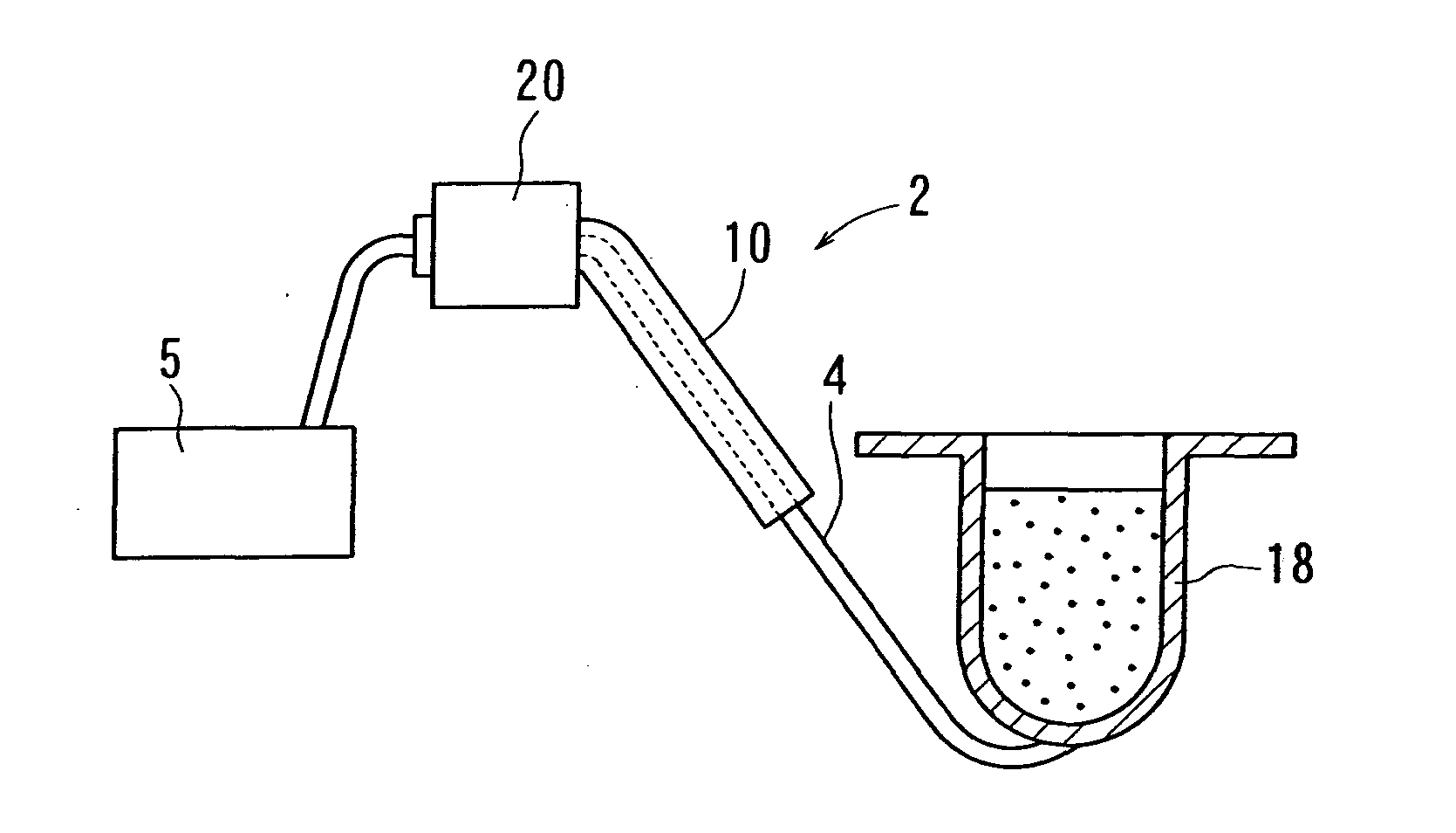
A preferred structure is illustrated in FIG. 7. FIG. 7 shows a float 28 installed on the transport conduit 4 via a mounting unit 30. In this example, the float 28 includes a catch 28a that is caught on the upper edge of the mounting unit 30, and a contact member 28b that comes into contact with the molten metal inside the transport conduit 4. The catch 28a includes an indicator 29 that indicates the displacement of the float 28. The catch 28a of the float 28 is engaged with the upper edge of the mounting unit 30 to enable the float 28 to rock, and at the same time, the mounting unit 30 has a space 30a that can accommodate the maximum displacement of the float 28 without hindering its rocking movements. In this example, the float 28 itself serves as a detection member, and the displacement produced by the contact member 28b is transmitted as is to the catch 28a and the indicator 29, and thus is easily comprehended from outside. Note that it is of course possible to use a separate detection member to transmit the displacement of the float to the outside.
Because of this, as shown in FIG. 8 and FIG. 9, it is preferred that the rotary vane 22 be snapped into the transport conduit 4, primarily using tapered concave and convex members. More specifically, a tapered fitting hole 42 is provided in the transport conduit 4 in which the caliber thereof grows smaller toward the interior of the conduit, a cap 44 is employed that has a tapered convex portion 46 that is fitted to and matches the fitting hole 42, and a through hole 48 in which the shaft 24 can be mounted is provided in the convex portion 46. In this way, the rotary vane 22 can be mounted inside the transport conduit 4 by fitting the aforementioned cap 44 into the aforementioned fitting hole 42, and thus the precision of the seal on the conduit 4 can be improved and maintained by means of a mechanical fitting.
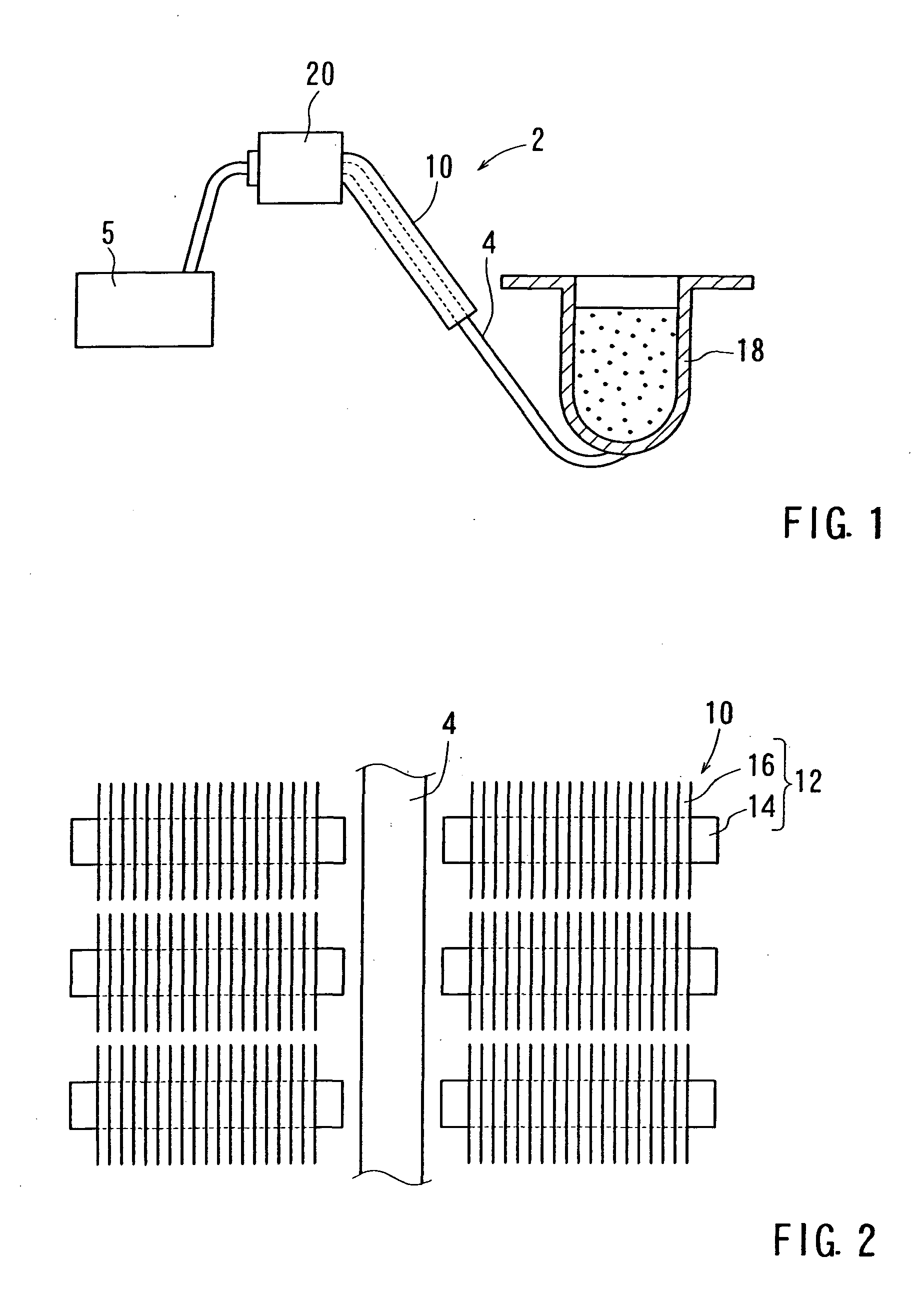
First, molten metal in the molten metal holding furnace 18 is supplied to a cavity for a metal cast by operating the electromagnetic pump 10. As the molten metal is transported, the rotary vane 22 provided inside the transport conduit 4 rotates, and the rotational frequency thereof is detected by the detector 32. If the relationship between the rotational frequency and the amount of molten metal has been established, the operating time of the electromagnetic pump 10 and the power supply are adjusted based on the rotational frequency, such that the desired time of rotation of the rotary vane 22 and/or the rotational frequency thereof are obtained in order to supply a predetermined amount of molten metal to the cavity. In this way, a constantly accurate amount of molten metal can be supplied to the cavity of the metal cast, and a cast metal object can be manufactured with a high degree of precision.
For example, as shown in FIG. 4, the rotational frequency detector can be a pulse generator 32 that is arranged such that when the rotation of the shaft 24 inside the transport conduit 4 is transmitted, the pulse generator 32 detects the rotation and generates a pulse. Note that by transmitting the pulses generated by the pulse generator 32 to a device equipped with a pulse counter mechanism, the rotational frequency can be easily detected.
Furthermore, as shown in FIG. 4, the drive force of the external motor 40 can be transmitted to the shaft 24, and the rotary vane 22 can be formed so that it is rotatively driven from the exterior thereof. In this way, sufficient rotational force can be conferred to the rotary vane.
Furthermore, in situations in which a detection means for detecti...

Benefits of technology

According to this method, a highly precise cast metal object can be easily obtained.
In addition, another aspect of the present invention provides, a measuring device for a molten metal supply device that uses an electromagnetic pump having: a rotary vane that is provided in a molten metal transport conduit and which is rotated in accordance with the movement of molten metal; and a detector that detects the rotational frequency of the rotary vane. In this measuring device, it is further preferred that a means of detecting the amount of molten metal inside the transport conduit be provided in the transport conduit. According to this device, the amount of molten metal transported can be measured with a high degree of accuracy.
In addition, the present inventors have studied the decrease in the non-wettability of aluminum titanate ceramic wi...

Abstract

An electromagnetic type molten metal supply device having superior accuracy in supplying molten metal. This device is comprised of a rotary vane that rotates in accordance with the movement of molten metal inside a molten metal transport conduit, and the amount of molten metal being transported can be measured by detecting the rotational frequency of the rotary vane.

Application Domain

Molten metal pouring equipmentsMolten metal supplying equipments +3

Technology Topic

Image

  • Molten metal supply device and aluminum titanate ceramic member having improved non-wettability
  • Molten metal supply device and aluminum titanate ceramic member having improved non-wettability
  • Molten metal supply device and aluminum titanate ceramic member having improved non-wettability

Examples

  • Experimental program(3)

Example

Embodiment 1: Production of the Aluminum Titanate Ceramic
The aluminum titanate (Al2TiO5) base powder that was used was Marusu Yuuyaku's TA-2 (containing 5 wt % SiO2) . Water and an alumina ball were added to the base powder, the weight ratio of raw material : alumina ball : water was adjusted to 1:1:0.7, and this mixture was mixed in a ball mill for 63 hours. After that, the Al2TiO5 slurry was passed through a sieve (200 mesh), and water was extracted therefrom with a filter press to obtain an Al2TiO5 press cake.
To this press cake were added suitable amounts of water, a deflocculating agent (manufactured by Chukyo Yushi, product name: D-305), a binder (manufactured by Chukyo Yushi, product name: WE-518), and the slurry density was adjusted to 2.1 to 2.3 g/cm3.
After this, this slurry was poured into a plaster mold, and after it was cast, it was dried at room temperature to obtain a green compact. Two types of green compact were produced, the ladle shape shown in FIG. 13 and the vessel shaped bonded set (2 members) that comprise the bonded portion shown in FIG. 14. As shown in FIGS. 13(a) and (b), a ladle-shaped body 102 is a hemispherical vessel comprising one sprue; and the bonded set, as shown in FIG. 14(a), is a vessel 106 consisting of 2 members vertically disposed with respect to each other, that has as shown in FIG. 14(b), a tapered inner circumferential surface 110 in the opening of the lower member 108, and an upper member 112 that is formed into an approximately annular body that comprises an outer circumferential surface 114 that fits into the inner circumferential surface 110. The two vertically arranged members 112, 108 form an integral vessel when fitted together.
Furthermore, by baking the green compacts for one hour at 1600° C. in the presence of air, an Al2TiO5 ceramic sintered compact was obtained.

Example

Embodiment 2: Forming the Al2O3 Layer and the MgAl2O4 Layer
The Al2TiO5 ceramic sintered compacts obtained (a total of three types) were dip-coated in Aluminasol (manufactured by Nissan Chemical, product name: Aluminasol 200 or Aluminasol 520), and then dried at room temperature. After that, an α-Al2O3 layer having a thickness of 5 μm was formed over the entire surface of each Al2TiO5 ceramic sintered compact by baking each at 1100° C. for one hour in the presence of air.
After that, each compact was immersed for one hour in a molten aluminum alloy (A4C: composition shown in Table 1), 700° C.) that contains a trace amount of Mg (0.5 wt %). In this way, the α-Al2O3 layer on the surface of the Al2TiO5 ceramic reacts with the Mg in the molten A4C, and a monophase MgAl2O4 layer is formed on the surface of the Al2TiO5 ceramic. The thickness of the MgAl2O4 layer is the same as the 5-μm thickness of the α-Al2O3 layer before being immersed in the molten A4C.
Note that the presence of α-Al2O3 (before immersion in the molten metal) or MgAl2O4 (after immersion in the molten metal) on the surface of the Al2TiO5 ceramic sintered compacts was confirmed by X-ray diffraction analysis. In addition, the thickness of each layer was measured by energy dispersion type X-ray diffraction analysis.

Example

Embodiment 3: Evaluation of Non-wettability
(1) Wetting Angle
The wetting angle is measured in order to evaluate the non-wettability of the Al2TiO5 ceramic sintered compact with respect to the molten aluminum alloy (A4C).
The following three types of Al2TiO5 ceramic test pieces were used. In other words, i) a test piece in which the surface of the sintered compact produced in Embodiment 1 was cut into a 25 mm×25 mm×6 mm piece, surface-finished to 25 mm×25 mm (thickness of 5 mm) by means of a #800 diamond grindstone, and had a surface roughness (center line average roughness) of approximately 3 μm; ii) a test piece with the same surface finish, on whose surface an α-Al2O3 layer having a thickness of 5 μm was formed according to Embodiment 2; and iii) a test piece obtained by immersing an Al2TiO5 ceramic sintered body on which an α-Al2O3 layer had been formed in a molten aluminum alloy (A4C, 720 degrees C.) for 50 hours in order to change the surface of the α-Al2O3 layer to an MgAl2O4 layer.
An MH-type guided interlock observation device produced by Union Optical was used to measure the wetting angle. The aforementioned test pieces were placed on the device's heater with their final processed surfaces (25 mm×25 mm surfaces) facing upward, and then cylindrical pieces of aluminum alloy (A4C) that were 10 mm in diameter and 10 mm in length were placed on these surfaces. After that, the temperature was raised 5° C./min from room temperature to 700° C. in an argon gas atmosphere (flow volume 2500 cc/min), and was maintained at that point for 30 seconds. After that, at 700° C., a lamp light was radiated onto the aluminum alloy and test pieces, the images produced were projected onto a screen, and the contact angle between the surface of each test piece and the aluminum alloy was measured from these images.
The wetting angle at 700° C. was as noted below. The Al2TiO5 sintered compact=120 degrees, the α-Al2O3 coated Al2TiO5 sintered compact=135 degrees, and the MgAl2O4 coated Al2TiO5 sintered compact=128 degrees; thus, it is clear that the non-wettability of the Al2TiO5 sintered compact with respect to the aluminum alloy increases due to the α-Al2O3 coating and the MgAl2O4 coating.
(2) Non-wettability Lifespan
Two kg of 700° C. molten aluminum alloy (A4C) was poured into a ladle-shaped Al2TiOO5 ceramic sintered compact (comprising an α-Al2O3 layer), and after holding it there for 50 seconds, the molten metal inside the ladle was discharged. This process was repeated until the molten metal stuck to the inner wall of the ladle and remained there, even after the molten metal had been discharged. The results were that the ladle produced in the embodiment had absolutely no molten metal stuck thereto after 12,000 repetitions of this process. Because of this, it is clear that this ladle possesses and can retain excellent non-wettability. In addition, the presence of the MgAl2O4 layer on the inner wall of the ladle was confirmed after 12,000 repetitions of the process.
In contrast, subjecting an Al2TiO5 ceramic ladle not having an Al2O3 layer formed thereon resulted in molten metal sticking thereto after 2000 repetitions of the aforementioned process.
(3) Sealing Characteristics of a Bonded Body Comprising Bonded Sections
Each member of the Al2TiO5 ceramic bonded set having an α-Al2O3 layer thereon was fitted together at the bonding positions to form a bonded body, and the outer circumference of the bonding position was secured with a stainless steel band (width 20 mm) via an alumina fiber sheet (manufactured by Mitsui Mining Materials, product name: Almax). A piece of aluminum alloy (A4C) was placed inside the bonded body, and then its temperature was raised (20° C./min) in an argon gas atmosphere (flow volume 100 cc/min) until the temperature reached 720° C. and the aluminum alloy melted. After melting, the temperature was maintained at 720° C. for one hour, and then the temperature was reduced (20° C./min). This process was repeated 50 times.
The result of this was that absolutely no molten metal was observed leaking from the bonded position while the process was being repeated. In addition, absolutely no molten metal stuck to the molten metal contact positions on the inner wall of the bonded body, thus confirming that the bonded body retained excellent non-wettability. Note that the formation of an MgAl2O4 layer on the surface of the molten metal contact portions inside the bonded body was confirmed.
According to the present invention, conferring and retaining the non-wettability of aluminum titanate ceramic with respect to molten aluminum alloy can be easily achieved.

PUM

PropertyMeasurementUnit
Force
Pressure
Volume
tensileMPa
Particle sizePa
strength10

Description & Claims & Application Information

We can also present the details of the Description, Claims and Application information to help users get a comprehensive understanding of the technical details of the patent, such as background art, summary of invention, brief description of drawings, description of embodiments, and other original content. On the other hand, users can also determine the specific scope of protection of the technology through the list of claims; as well as understand the changes in the life cycle of the technology with the presentation of the patent timeline. Login to view more.

Similar technology patents

Nitride semiconductor laser chip

ActiveUS20100316082A1Easily obtainSufficient reliabilityOptical wave guidanceLaser detailsResonatorLaser
Owner:SHARP FUKUYAMA LASER CO LTD

Plant information display apparatus and method

InactiveUS20090228839A1Good operabilityEasily obtainProgramme controlTotal factory controlData selectionSoftware selection
Owner:YOKOGAWA ELECTRIC CORP

Classification and recommendation of technical efficacy words

  • Easily obtain
  • High degree of accuracy

Methods and Compositions For Preparing Pancreatic Insulin Secreting Cells

InactiveUS20080241107A1Easily obtainBiocidePancreatic cellsTransdifferentiationPancreatic structure
Owner:BOARD OF RGT THE UNIV OF TEXAS SYST

Direct metal laser sintered flow control element

ActiveUS20090183790A1Reduce velocity of fluidHigh degree of accuracyAdditive manufacturingValve members for absorbing fluid energyEngineeringMetallic materials
Owner:CONTROL COMPONENTS INC
Why Eureka
Try Eureka