

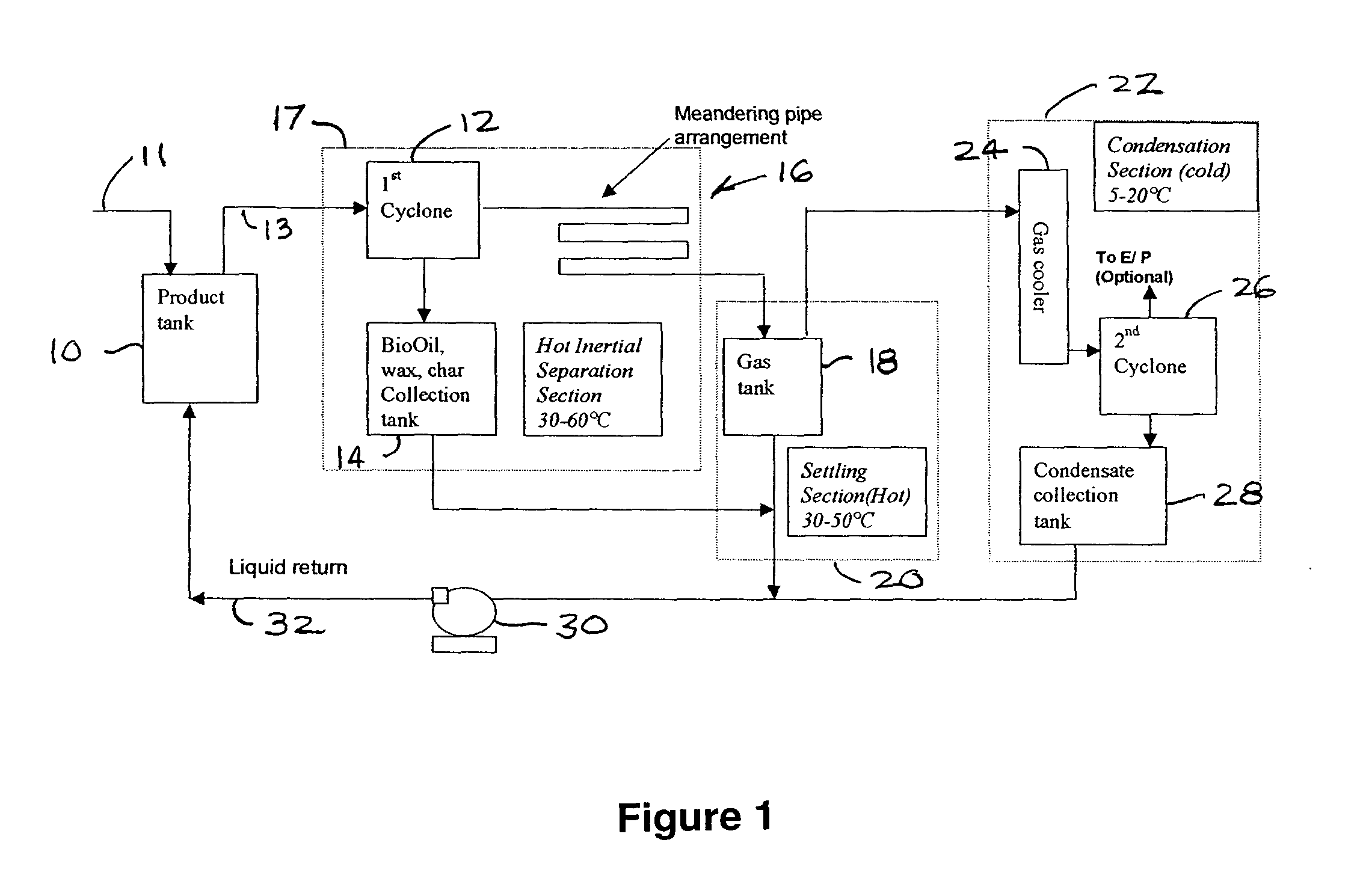
Apparatus for separating fouling contaminants from non-condensable gases at the end of a pyrolysis/thermolysis of biomass process
a technology of biomass pyrolysis and apparatus, which is applied in the direction of gas purification by non-gaseous materials, special form destructive distillation, coking carbonaceous materials, etc., can solve the problems of inefficient normal surface condensers, extreme fouling, and inefficient operation of separation equipmen
- Summary
- Abstract
- Description
- Claims
- Application Information
AI Technical Summary
Benefits of technology
Problems solved by technology
Method used
Image

Examples
Embodiment Construction
(APPLICATION OF THE INVENTION)
[0056] The following tables, illustrate several examples of thermolysis runs and the collector's performance.
TABLE 1Sample examples of Hot Back End collection by devicesin pyrolysis / thermolysis unit # 2 (15 tonne / daypre-commercial plant)Percent of total BioOil productioncollected in each vesselMeanderingGas coolerProductpipe and gasandFeedtankCyclone#1tankCyclone #2whitewood81.53.18.06.4whitewood77.14.45 12.8 Whitewood / 79.06.15.07.9barkWhitewood / 83.05.34.26.4barkBioOilViscous,Viscous,YellowishBioOil, wax,BioOil, wax,condensateCondensableCondensableFree ofand charand charBioOil andwax
[0057]
TABLE 2Sample examples of Hot Back End collection by devices inpyrolysis / thermolysis unit # 1 (two tonne / day pilot plant)Percent of total BioOil productioncollected in each vesselMeanderingProductpipe and gasFeedtankCyclone#1tankGas coolerFine79.63.85.810.8bagasseSemi-70.710.711.27.3coarsebagasseCoarse5312.513.619.3bagasseWhitewood / 62.820.66.96.9barkWhitewood / 64.120...
PUM
| Property | Measurement | Unit |
|---|---|---|
| Length | aaaaa | aaaaa |
| Fraction | aaaaa | aaaaa |
| Fraction | aaaaa | aaaaa |
Abstract
Description
Claims
Application Information