
Metal-backed printing blanket

Active Publication Date: 2005-02-24
REEVERS BROTHERS INC
View PDF7 Cites 21 Cited by
  • Summary
  • Abstract
  • Description
  • Claims
  • Application Information

AI Technical Summary

Benefits of technology

[0016] The above-identified problems have been solved by eliminating the plastic adhesive foil and other packing of the metal backed blanket. Cleaning solvents and other commonly used printing chemicals do not form bubbles underneath the printing blanket when the blanket is applied directly to the blanket cylinder. To prevent the corrosion that would otherwise take place, the blanket cylinder contact surface of the metal backed blanket is specially treated. This treatment takes the place of the packing in the prevention of slippage of the belt around the drum, and also prevents corrosion of the drum due to application of the solvents, adhesives, and other chemicals. Unlike the packing materials of the prior art, the special backside treatment of the current invention does not bubble when it comes in contact with the adhesives and solvents that are used in the application of the metal-backed blanket to the drum. Pretreating the metal backed blanket with the specialized treatment reduces the downtime, and the complexity of replacing the printing blanket.
[0017] The specialized treatment applied to the metal backed blanket can be a very thin plastic film. The film is applied to the metal backed blanket in such a manner as to prevent the absorption of adhesives, solvents, and other printing chemicals by the metal backed blanket. This can be accomplished by thermowelding, plastic spray on techniques, plasma treatment, or any other method that is known in the art. The film is generally applied in a thickness of from 5 to 250 μm, preferably from 5 to 100 μm, and optimally from 25 to 100 μm. The plastic adhesive foil can be made from such materials as polyolefins, polyesters, polyurethanes, phenolic compounds, polyethylene, polystyrene, polypropylene, polymethyl methacrylat,e polyamides, nylon, polyvinyl chloride, polyvinyl fluoride, or the like.

Problems solved by technology

This process presents problems however in that the packing procedure is time consuming, resulting in down time for the printing equipment.
Further, once positioned on the cylinder, the packing paper tends to slide, slip, and / or fold which may render the blanket surface nonuniform and resulting in poor printing results.
Further, when a blanket must be replaced, the time consuming packing operation must be repeated for a new blanket.
No pack blankets are manufactured to very precise gauges so that one can be installed directly onto a cylinder with the correct amount of interference.
In offset lithography as well as other printing operations, the printing plate and blanket cylinders are subject to corrosion and rust because of exposure to inks, water, and chemicals used in cleaning up the machinery.
However, such nickel- and chrome-plated cylinders have not worked well in conjunction with no pack blankets.
While chrome plating is more resistant to removal than nickel, it too is subject to wear.
The areas on the cylinder surface where the plated metal is removed are then subject to rapid corrosion and / or oxidation.
These adhesive foil coatings are not without problems.
Exposure to the same inks, water, and chemicals that cause the corrosion / oxidation problems in the metal plated cylinders can cause bubbles to form between the polyester film, and the surface of the cylinder.
These solvents penetrate the foil coating from either side of the cylinder, resulting in the bubbling and delamination of the foil coating.
However, flaws and imbalances in the printing blanket become magnified as the rotational speed of the blanket cylinder is increased.
In particular, high-speed rotation of a cylinder with a cylinder gap can result in undesirable levels of vibration and shock loading.
The resultant eccentric loading increases vibration during high-speed rotation of the cylinder, to the detriment of print quality.
Fabric backed printing blankets are particularly susceptible to the deleterious effects of vibrations during high speed operations, such as slipping and smearing of ink as it is transferred from one surface to another.
Furthermore, high-speed operations increase shock loading, which occurs when the edges of the gap contact the adjoining printing plate.
This repetitive impact causes the cylinder and the mounted blanket to bounce, causing the ink to streak and increasing wear on both the blanket and the cylinder.

Method used


Image

  • Metal-backed printing blanket
  • Metal-backed printing blanket
  • Metal-backed printing blanket

Examples


Embodiment Construction

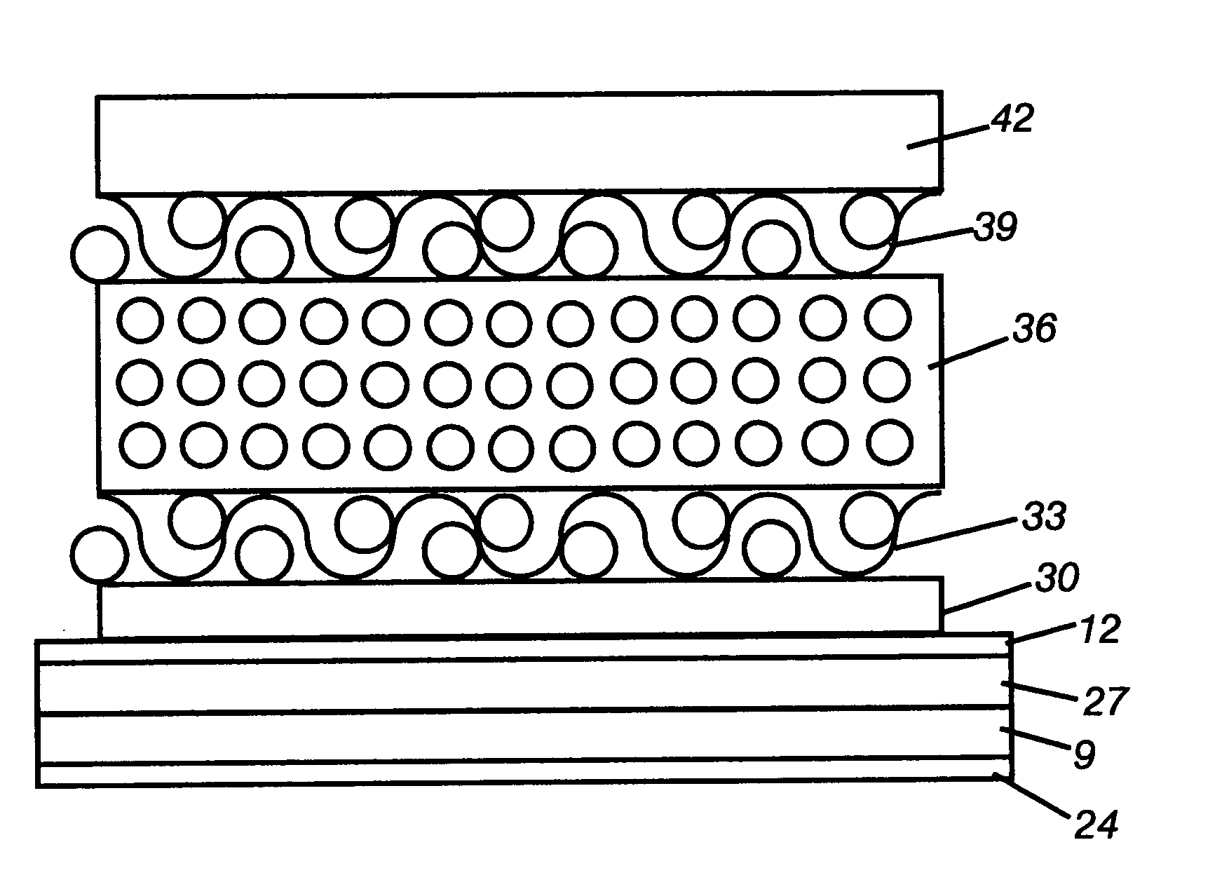
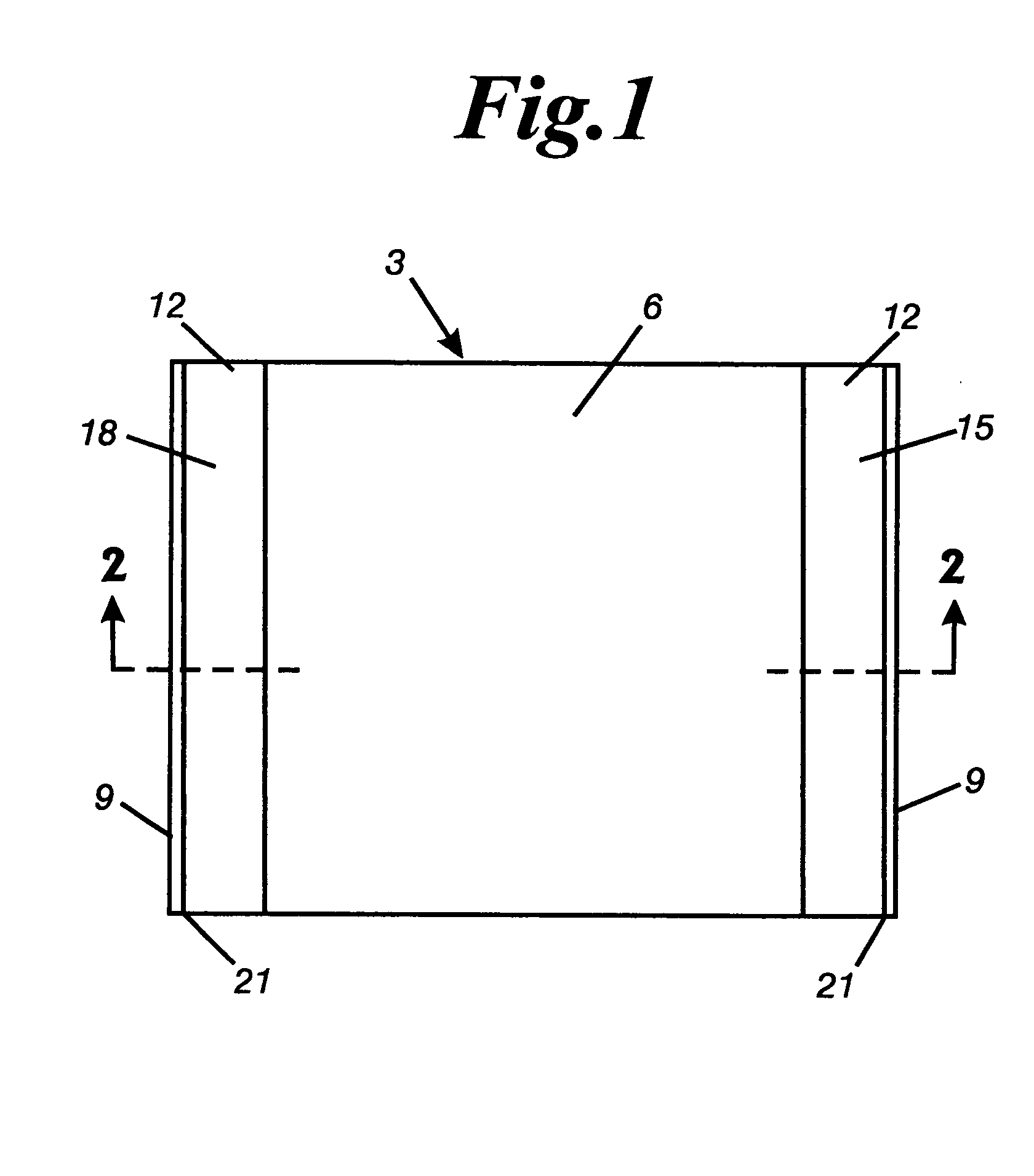
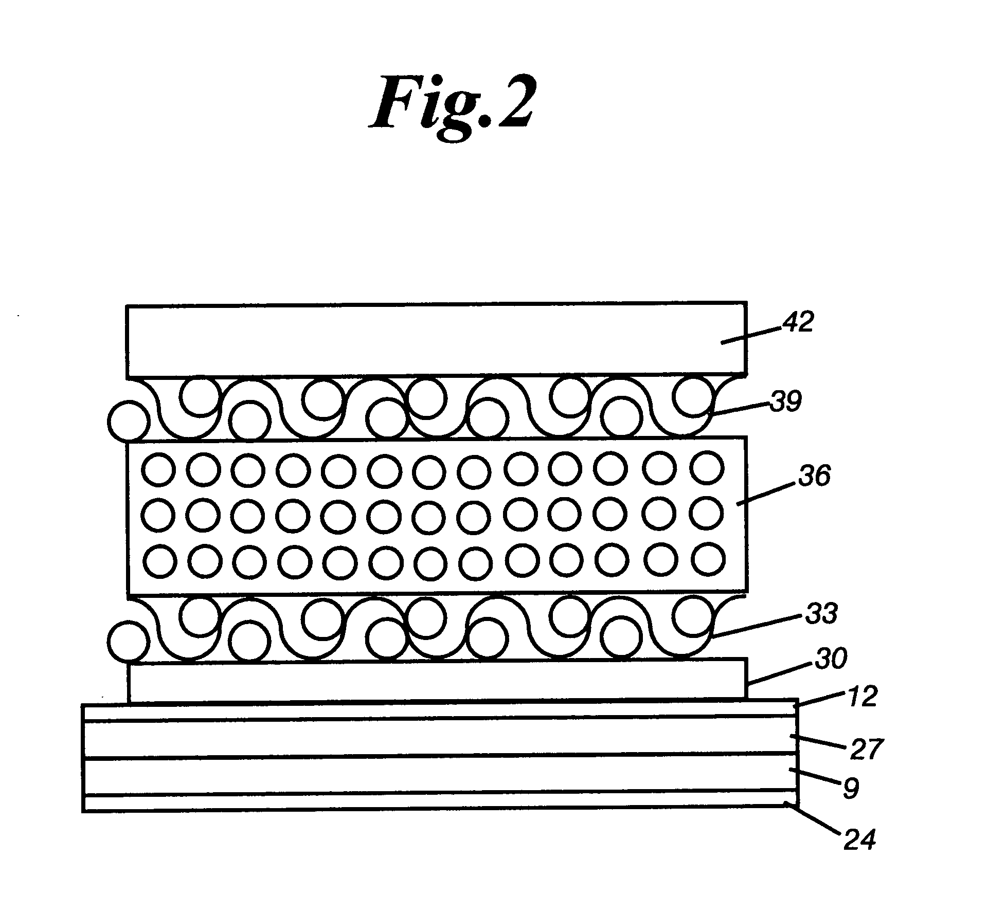
[0029]FIG. 1 illustrates an embodiment of a printing blanket 3 of the present invention, which shows generally the compressible printing blanket 6, an anti-slip layer 12, and a terminal portion 21 of a metal base plate 9 with a specialized coating layer (shown in FIGS. 2 through 4) applied to the backside thereof, lying in a flattened position. For convenience of understanding the invention, FIGS. 2 through 4 provide greatly exaggerated cross-sectional views of the printing blanket 3 showing the different layers of a preferred embodiment of the invention. These layers, together with their associated features, are discussed below.

[0030] For purposes of the present discussion, the terms “bottom” and “lower” and the like are used to refer to that portion of an individual layer or set of layers that is most nearly adjacent to the cylinder upon which the blanket of the present invention is mounted. Conversely, the “top” or “upper” portion of an individual layer or set of layers is that ...


PUM


Abstract

A metal backed printing blanket for mounting on a blanket cylinder that includes a gap, the printing blanket having a thin metal base plate with top and bottom surfaces and ends which include leading and trailing edges adapted for engaging the gap in the cylinder; a compressible, elastomeric printing blanket secured to the top surface of the base plate but not the ends and having an upper face adapted for contact transfer of ink to a printable substrate; and a specialized coating applied to the bottom surface to prevent deformation of the printing blanket and to prevent delamination of the printing blanket from a blanket cylinder. The method for making a metal backed printing blanket for mounting on such a cylinder is also disclosed.

Description

BACKGROUND OF THE INVENTION [0001] This invention relates to a printing blanket construction, and more particularly to a metal backed printing blanket construction having a specialized corrosion resistant treatment that is attached to the underside (or reverse) of the metal blanket. The type of blanket referred to herein is used primarily in offset lithographic printing, but may also find utility in other fields of printing. [0002] In offset lithography, a rotary cylinder is covered with a printing plate that normally has a positive image area receptive to oil-based inks and repellent to water and a background area where the opposite is true. The printing plate is rotated so that its surface contacts a second cylinder covered with a rubber-surfaced ink-receptive printing blanket. The ink present on the image surface of the printing plate transfers, or offsets, to the surface of the blanket. Paper or other sheet stock to be printed is then passed between the blanket-covered cylinder ...

Claims


Application Information

Patent Timeline
IPC IPC(8): B41N10/04B41N10/06
CPCB41N10/04B41N10/06B41N2210/06B41N2210/14B41N2210/10B41N2210/04
Inventor INVERNIZZI, GIANPIETROBERGAMASCHI, SILVIAZENI, FAUSTO
Owner REEVERS BROTHERS INC
Features
  • Generate Ideas
  • Intellectual Property
  • Life Sciences
  • Materials
  • Tech Scout
  • Unparalleled Data Quality
  • Higher Quality Content
  • 60% Fewer Hallucinations
Learn More