Process for making hard pellicles

a technology of pellicles and processing equipment, applied in the direction of superimposed coating process, application, instruments, etc., can solve the problems of pellicles themselves bursting, transmission degrades to an unacceptable level, and the handling of photomasks is significantly more difficul

Inactive Publication Date: 2005-02-24
CORNING INC
View PDF5 Cites 20 Cited by
  • Summary
  • Abstract
  • Description
  • Claims
  • Application Information

AI Technical Summary

Benefits of technology

[0023] Preferably, the intermediate layer in step (ii) and the pellicle layer in step (iii) of the process of the present invention are deposited via chemical vapor deposition, plasma vapor deposition or sol-gel processes. Preferably, the chemical vapor deposition and plasma vapor deposition processes are selected from plasma enhanced chemical vapor deposition (PECVD), low pressure chemical vapor deposition (LPCVD), sub-atmospheric chemical vapor deposition (SACVD), ion-assisted electron evaporation, non ion-assisted electron evaporation and sputtering. More preferably, PECVD is used.
[0024] According to a preferred embodiment of th...

Problems solved by technology

Photomask handling is significantly more challenging for photolithography at wavelengths shorter than 193 nm, such as 157 nm, than for any previous generation of optical lithography.
Transmission degrades to an unacceptable level due to the darkening and ultimately the pellicles themselves often burst.
However, the polymer materials available can only reach 7 mJ/cm2 range before they have lost up to 45% of their transmission.
The lack of laser durability of the polymer materials renders it difficult to find a polymer pellicle solution.
Even if all of these requirements are met, there remains a problem of attaching the pellicles to the frame.
A first issue about the frame is flatness.
Since the thermal expansion coefficient for aluminum used currently in frames and the modified fused silica as a hard pellicle film are different, changes in temperature can cause distortions to the pellicle layer.
While most clean rooms are kept at a controlled temperature, there is no standard for clean room temperature, and no guarantee that the temperature will be the same from the point of manufacture to the point of use.
Unlike so...

Method used


Image

  • Process for making hard pellicles
  • Process for making hard pellicles
  • Process for making hard pellicles

Examples


Embodiment Construction

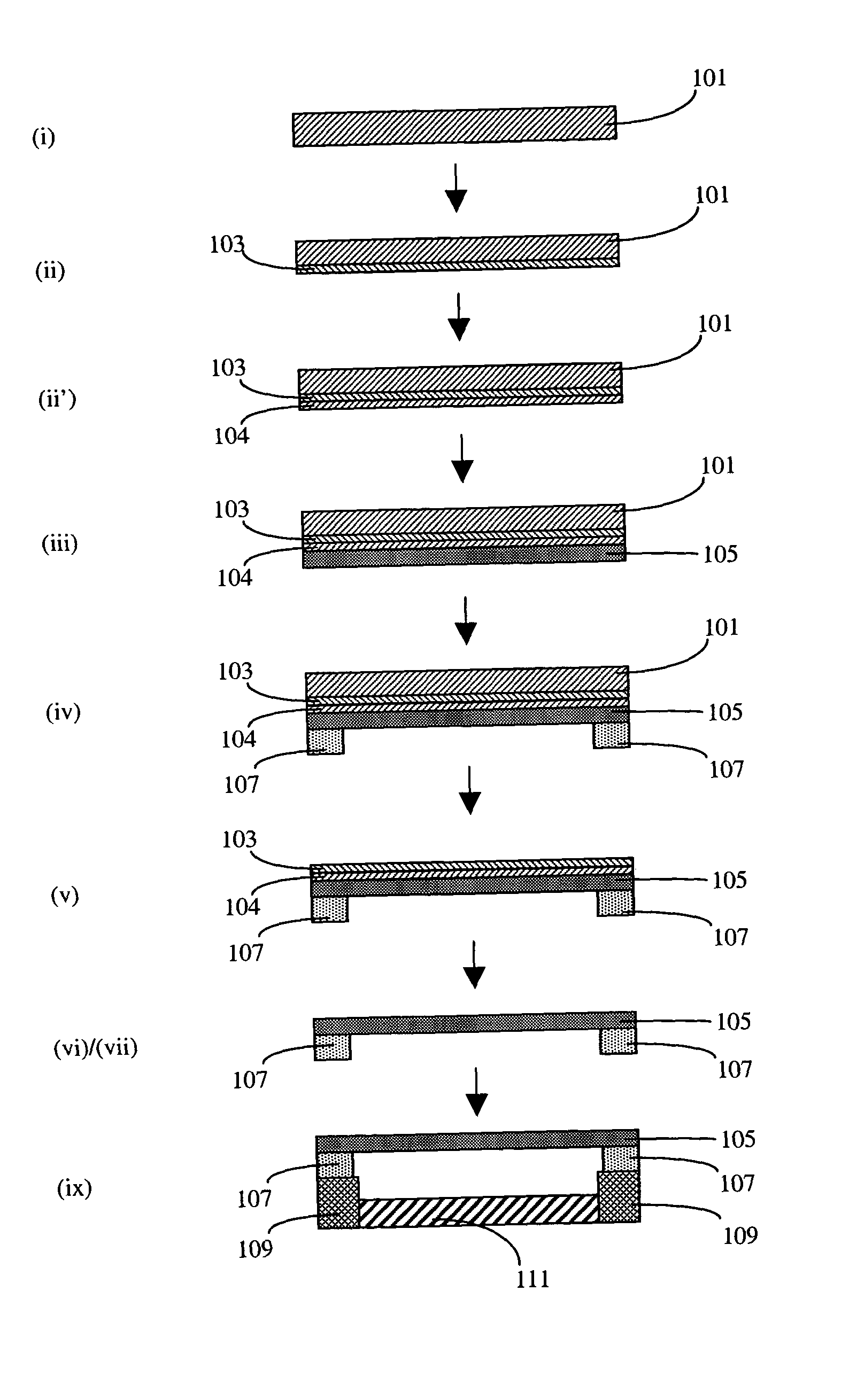
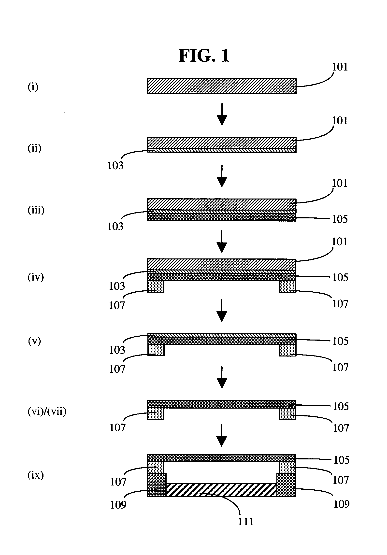
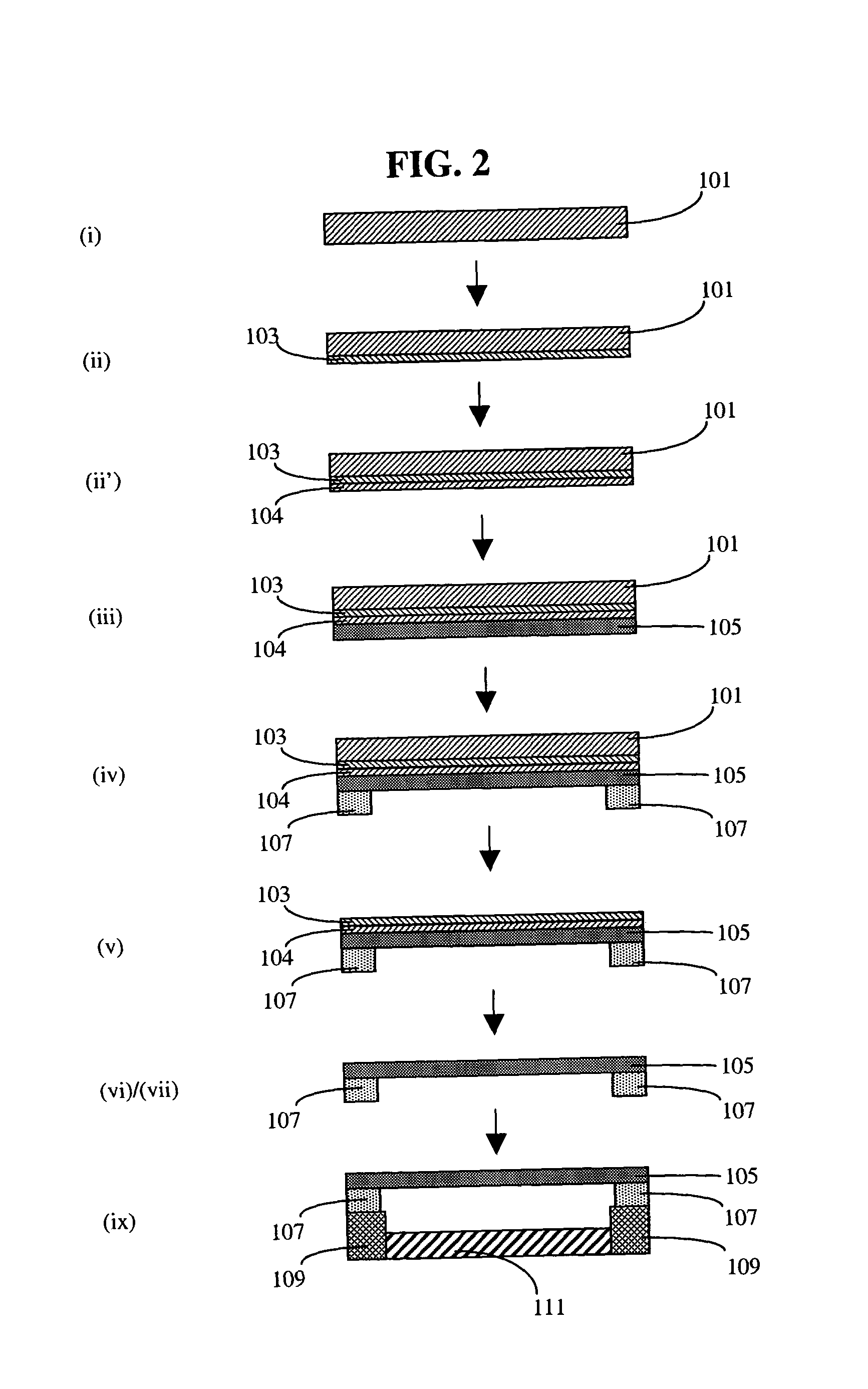
[0036] Pellicles serve as dust covers of reticles and protect the increasingly more expensive reticles from being contaminated in the lithographic process. Usually, a pellicle is an assembly comprising a thin pellicle layer mounted to a pellicle mount frame. Because the pellicle layer has a thin thickness compared to a relatively large surface area, the layer is sometimes called a membrane or a film. Typically, the pellicle layer has been made by stretching a thin (˜0.8 μm) polymer layer over an aluminum frame. As discussed above, this approach does not appear viable for 157 nm and shorter wavelength applications because the polymers rapidly degrade under the exposure of these wavelengths. An alternative was proposed by SEMATECH to use a hard pellicle comprised of silica or doped silica. Because silica has a higher modulus and density than polymer layers, initial efforts have focused on very thick (300-800 μm) silica plates to avoid sag, which causes wavefront distortion. The leadin...


PUM

PropertyMeasurementUnit
Thicknessaaaaaaaaaa
Temperatureaaaaaaaaaa
Stress optical coefficientaaaaaaaaaa

Abstract

Disclosed is a process for making thin hard pellicle for photomasks used in projection photolithography. The process can be used for making thin hard pellicles comprising a pellicle layer having a thickness in the range of about 5 to 120 μm and a mount frame attached to the peripheral area of a surface of the pellicle layer. The pellicle layer can consist essentially of a material selected from silica, fluorine doped silica, aluminum doped silica, methylated silica, fluorinated and methylated silica, fluorinated aluminum doped silica, CaF2, MgF2, BaF2 and SiC. The mount frame is preferred to have substantially the same CTE of the pellicle layer to minimize stress caused by temperature change. The mount frame is preferred to be porous to the purging gas. The process for making the hard pellicle involves deposition of an intermediate layer comprising a hydrogenated amorphous silicon layer on a flat substrate, deposition of the pellicle layer on the intermediate layer, mounting the frame to the pellicle layer and the separation of the pellicle from the substrate by heat treatment.

Description

FIELD OF THE INVENTION [0001] The present invention relates to a process for making hard pellicles for photomasks. In particular, the present invention relates to a process for making thin hard pellicles for photomasks used for photolithography at 193 nm and shorter wavelength. BACKGROUND OF THE INVENTION [0002] Photomask handling is significantly more challenging for photolithography at wavelengths shorter than 193 nm, such as 157 nm, than for any previous generation of optical lithography. One of the greatest concerns is the solution for pellicle, which is the cover used to protect the reticle during the lithographic process. [0003] Soft polymeric pellicle materials good at 193 nm, such as fluorine polymers have been shown to have good transmission initially but soon degraded because of photochemical darkening when used at 157 nm. This is because the chemical bonds in the polymer absorb the high-energy 157 nm photons and begin to break. Transmission degrades to an unacceptable lev...

Claims


Application Information

Patent Timeline
IPC IPC(8): C23C26/00C23C28/00G03F1/14
CPCC23C26/00Y10T156/11G03F1/62
Inventor BELLMAN, ROBERT A.
Owner CORNING INC
Why Eureka
Try Eureka