

Interactive orthodontic care system based on intra-oral scanning of teeth
a technology of intra-oral scanning and orthodontic care, applied in the field of orthodontics, can solve the problems of extreme amount of time and labor, no way to confirm, and too expensiv
- Summary
- Abstract
- Description
- Claims
- Application Information
AI Technical Summary
Benefits of technology
Problems solved by technology
Method used
Image

Examples
Embodiment Construction
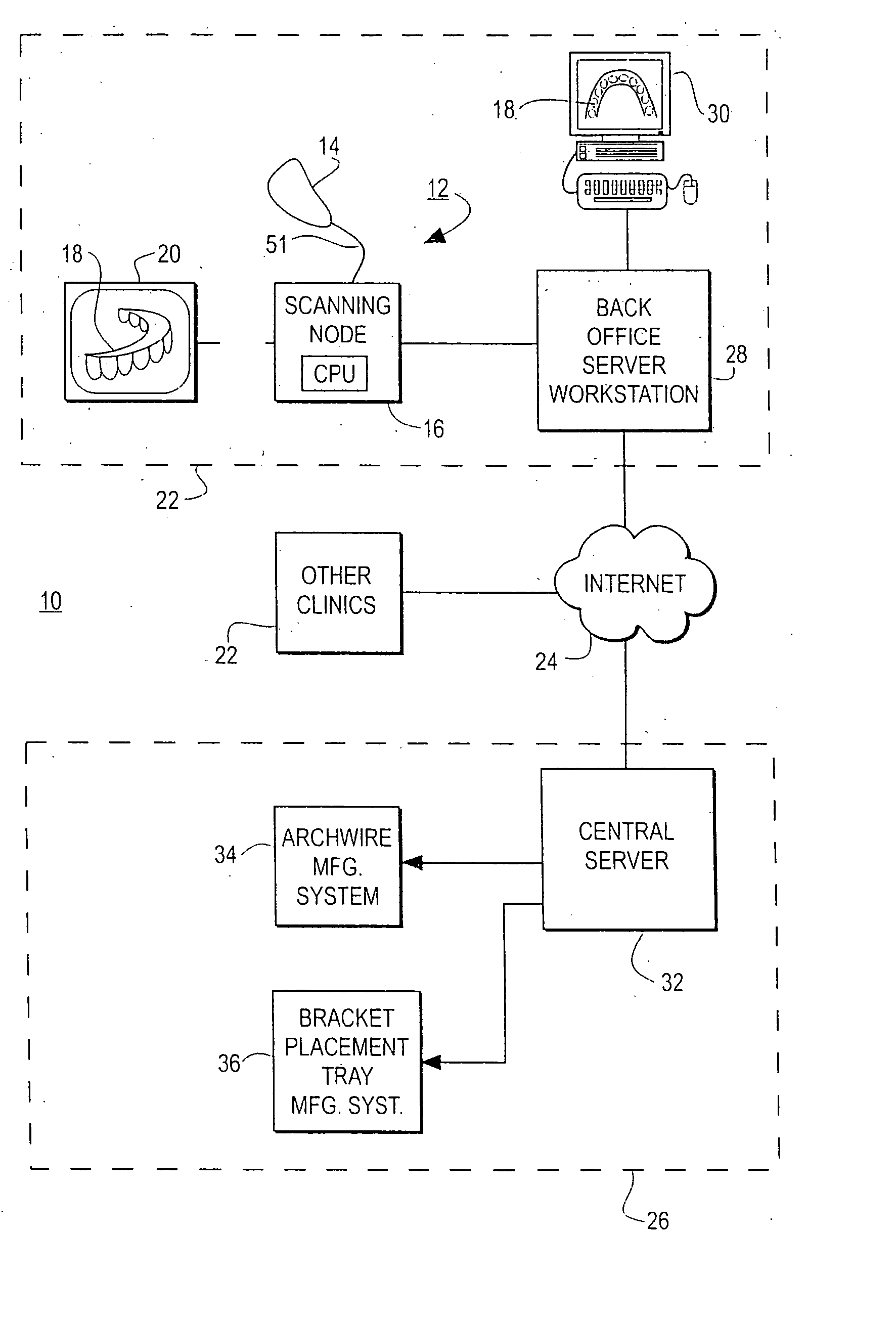
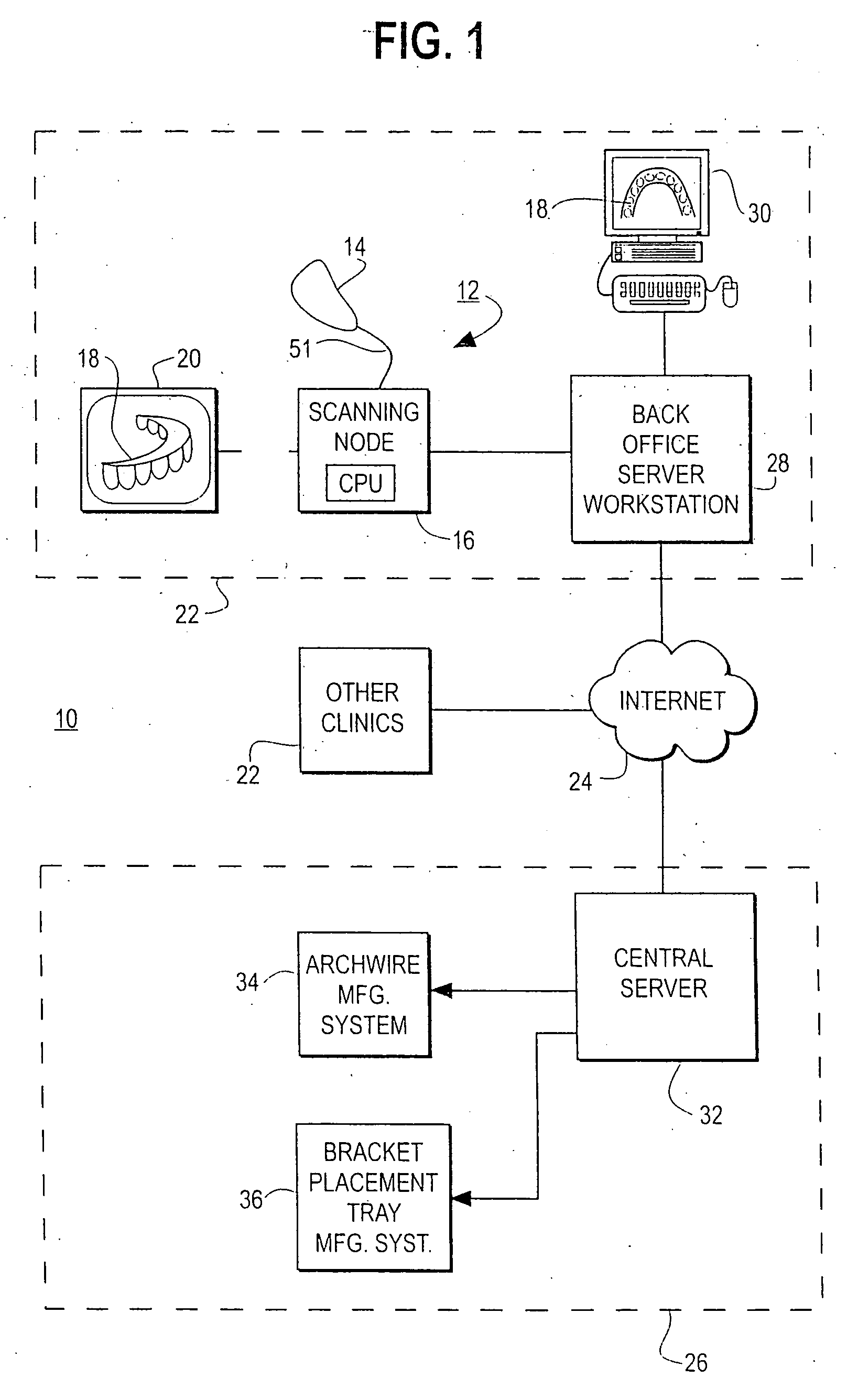
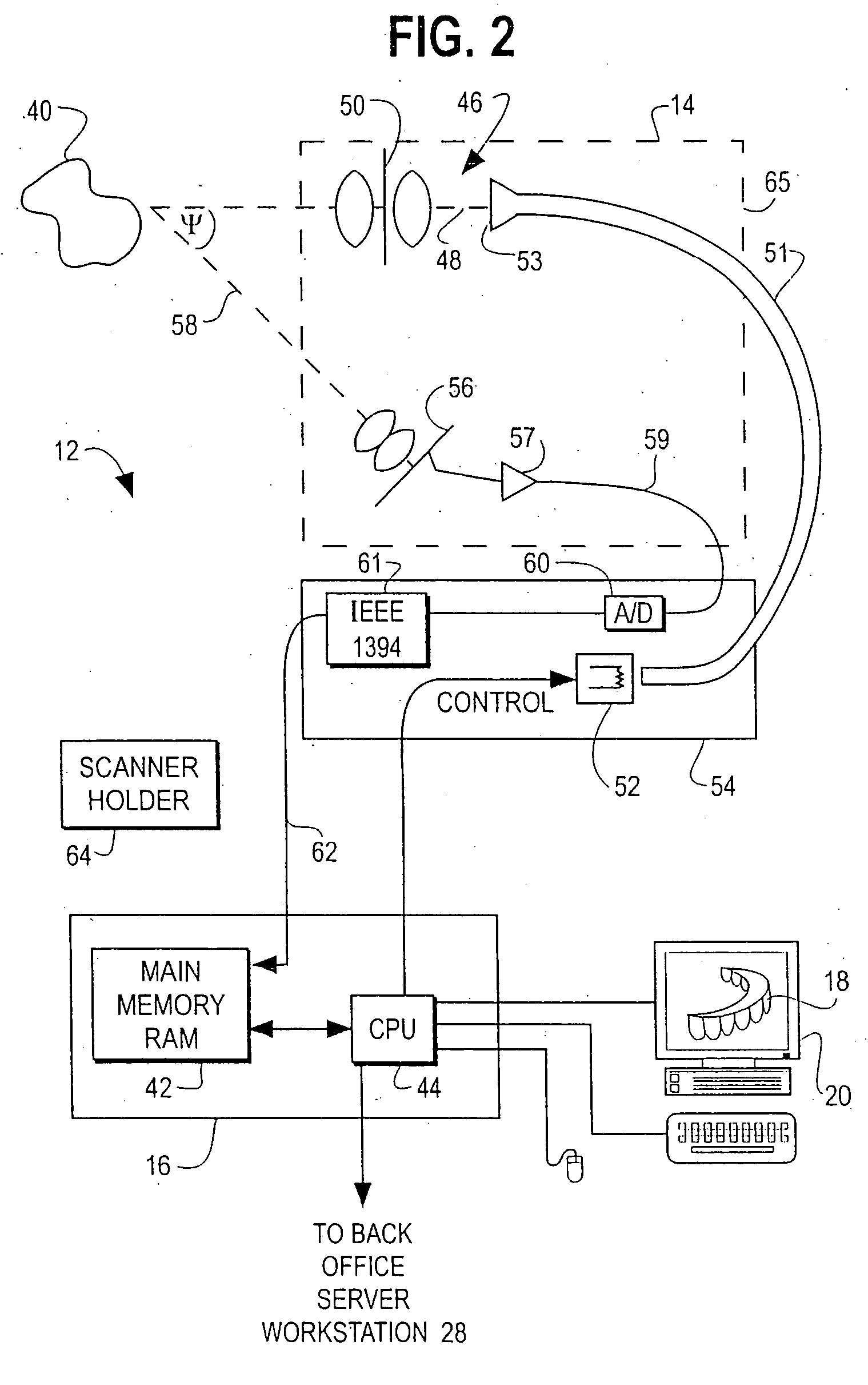
38Part 1. System Overview38Part 2. Three-Dimensional Image Capture47Scanner Manufacture and Calibration51Pattern Recognition65Decoding67Derivation of 3-D Point Cloud per Image73Part 3. Generation of Digital Impression75Entry point to registration79Frame to Frame Registration81Cumulative Registration of Entire Jaw89Segment registration96Landmarking97Separation of Teeth into Individual99Tooth Objects (tooth modeling)Part 4. Treatment Planning113Part 5. Appliance Manufacturing139Robot Design145Archwire Manufacture154Claims180Abstract191
BACKGROUND OF THE INVENTION
A. Field of the Invention
This invention relates generally to the field of orthodontics. More particularly, the invention relates to a computerized, interactive method and associated system for orthodontic treatment. The system includes a hand-held optical scanner capturing 3-dimensional information of objects, interactive computer-based treatment planning using three-dimensional tooth objects and user specified simulation o...
PUM
 Abstract
Description
Claims
Application Information