Integrated capacitor-like battery and associated method

a capacitor-like battery and integrated technology, applied in the direction of primary cells, vacuum evaporation coatings, chemical vapor deposition coatings, etc., can solve the problems of not being able being unable to meet the requirements of a single power supply, etc., to achieve the effect of improving the performance of the energy storage device and low internal resistan

Inactive Publication Date: 2005-03-03
CYMBET CORP
View PDF99 Cites 30 Cited by
  • Summary
  • Abstract
  • Description
  • Claims
  • Application Information

AI Technical Summary

Benefits of technology

[0016] In an embodiment as described herein, a film of an energy-storage device is fabricated by depositing a first material layer to a location on a substrate. Energized ions of a second material are directed to the first material to supply energy thereto, thereby assisting the growth of the crystalline structure of the first material. In some embodiments, the first material includes an intercalation material, which releasably stores ions therein. In one embodiment, the intercalation material is a lithium intercalation material. In energy-storage devices, and specifically in thin-film batteries, it is desirable to have large crystal size and a specific crystal orientation to improve electrical characteristics of the energy-storage device.
[0018] Another feature of the present invention is fabricating the electrolyte film by depositing a first material layer to a location on a substrate. Energized ions of a second material are directed to supply energy to the first material, thus assisting the growth of the crystalline structure of the first material. Another feature of the present invention includes fabricating the anode film by depositing a first intercalation material layer to a location on a substrate. Energized ions of a second material are directed to supply energy to the first material, thereby assisting the growth of the crystalline structure of the first material and controlling stoichiometry of the crystalline structure of the first material.
[0020] It is yet another aspect of the present invention to provide a seed layer on which an intercalation film is grown. The seed layer assists the formation of desired crystal structures to improve energy-storage device performance.
[0021] Another feature of the present invention includes fabricating an energy-storage device on any one of a plurality of different substrates. Some of the substrates have thermal degradation temperatures that are less than temperatures used for processes conventionally used for making thin-film batteries. It is another feature to provide systems and fabrication techniques that do not cause temperature degradation of a substrate or other layers thereon.
[0022] Another aspect of the present invention is overcoming the limitations of prior supercapacitor structures and fabrication procedures, the present invention provides, in particular, means for fabricating low internal resistance supercapacitor structures under economical manufacturing conditions. Such simple fabrication procedures enable the expanded use of these devices in a wide variety of configurations and applications, including combinations with integrated rechargeable battery energy sources of compatible composition and structure.

Problems solved by technology

One drawback to portable devices is the need to include the power supply with the device.
Sufficient battery capacity can result in a power supply that is quite heavy or large compared to the rest of the device.
Another drawback of conventional batteries is the fact that some are fabricated from potentially toxic materials that may leak and be subject to governmental regulation.
In this method, the magnetron source provides sputtered material having energy of about 1-3 eV, which is insufficient to crystallize the cathode material to form desirable crystal structures that encourage ion movement into and out of the cathode material.
The anneal step 221 complicates and adds cost to the fabrication of this type of solid-state battery.
Further, the anneal step 221 precludes the use of any material as the substrate or other part of the battery thus formed that is unable to withstand the high anneal temperature.
However, such extensive processing steps and high-energy consumption lead to economic undesirability of this approach.
Moreover, high temperature annealing limits the applicability of such a process to a narrow array of substrates and devices.
However, photovoltaic cells have not significantly displaced fossil fuels as an electricity producing means.
Two factors that have retarded the wide spread commercial acceptance of photovoltaics are costs of mass producing such cells and the low efficiency of energy conversion by the cells.

Method used

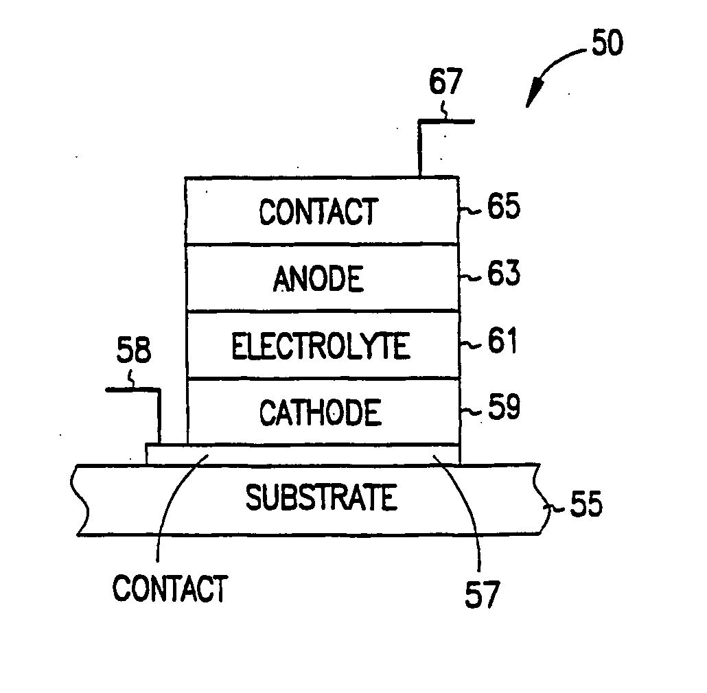
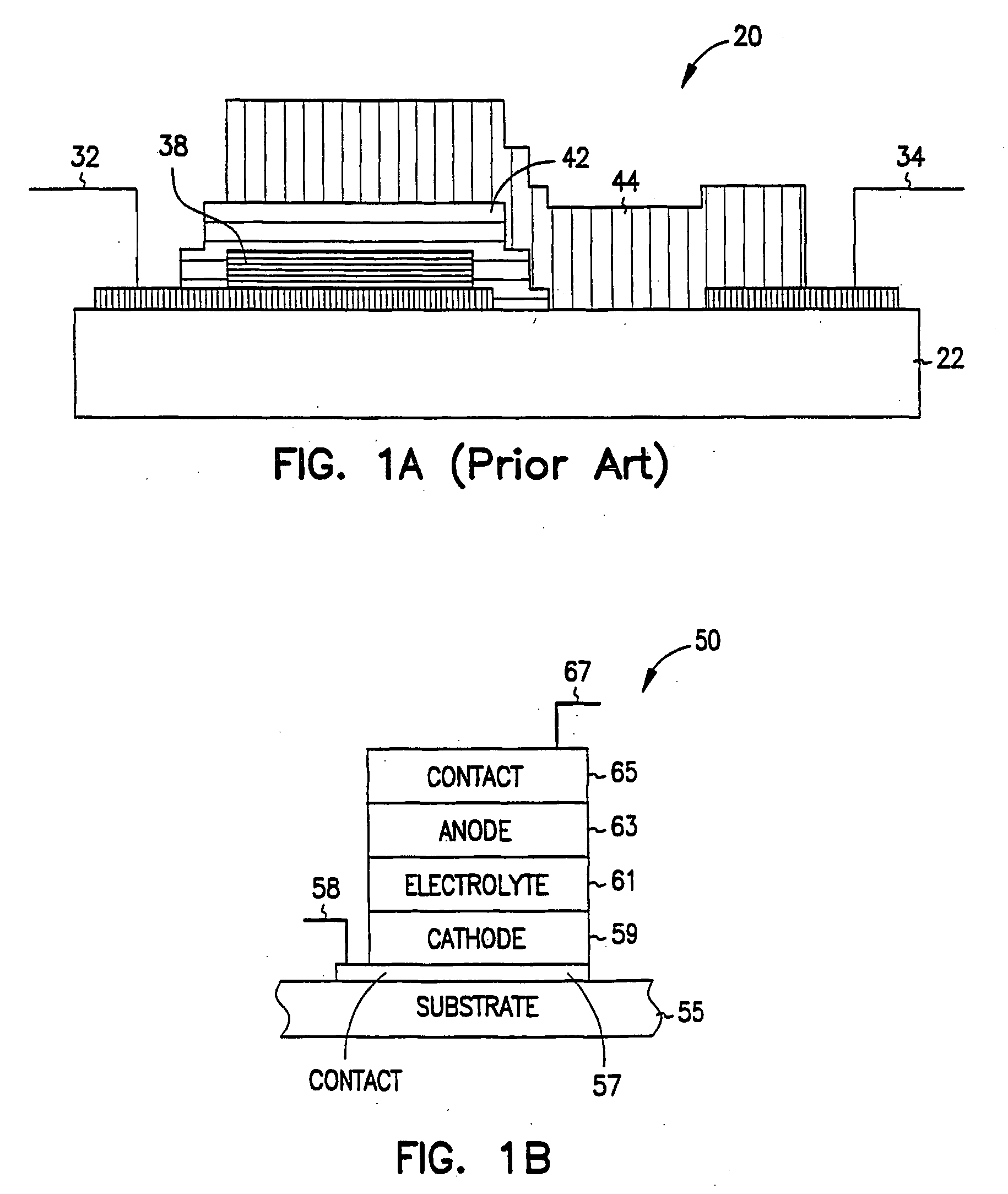
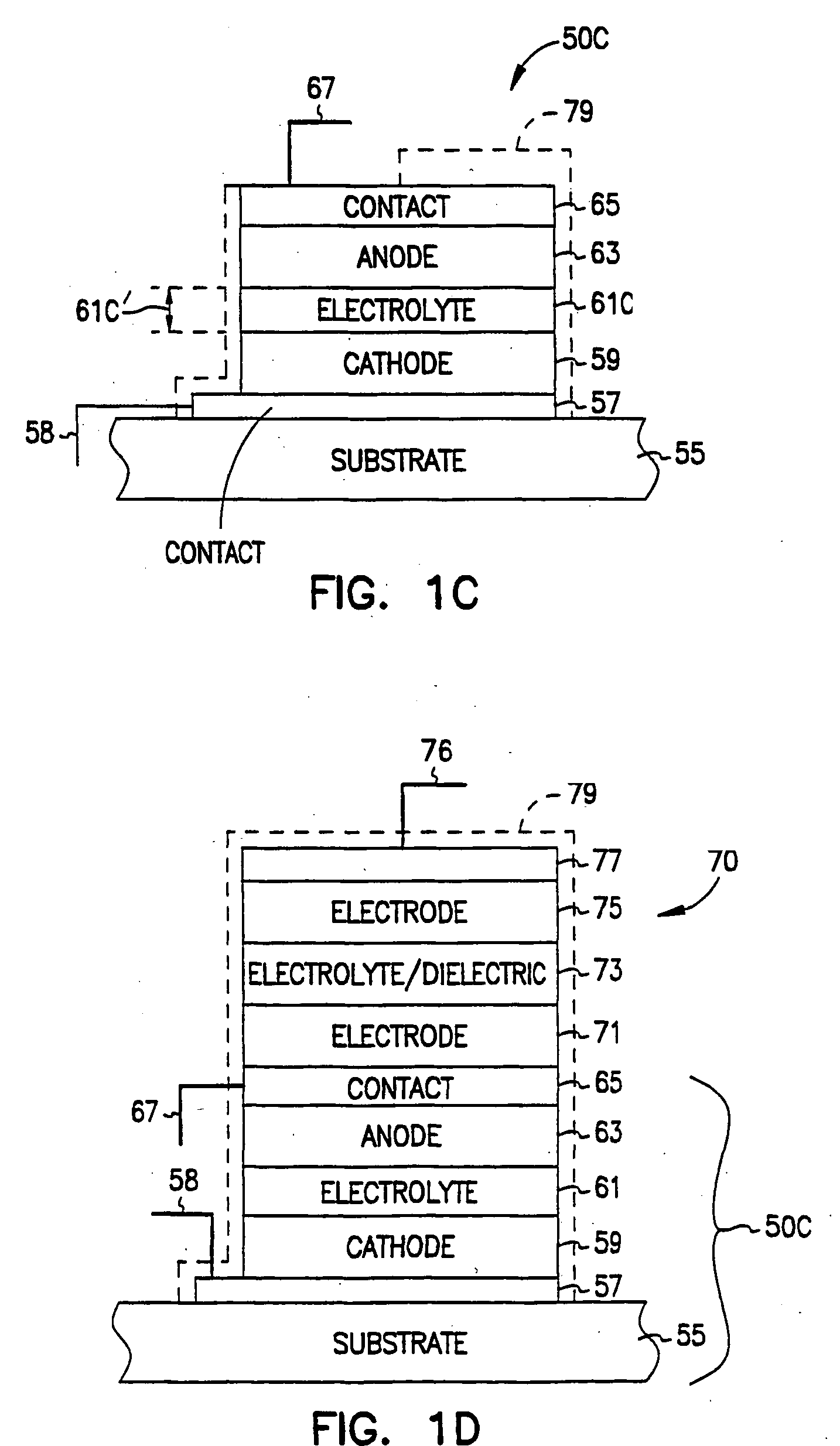

Image

  • Integrated capacitor-like battery and associated method
  • Integrated capacitor-like battery and associated method
  • Integrated capacitor-like battery and associated method

Examples


embodiment 2500

[0279]FIG. 25A shows a perspective view of an embodiment 2500 of the present invention having an integrated circuit 2510 overlaid with a battery 2320. In some embodiments, integrated circuit 2510 includes a top insulator layer 2511 having a plurality of vias or openings 2512 to the active surface of the integrated circuit 2510 (the side with devices and connectors). Two of these vias are used as contacts 2514 and 2515 between integrated circuit 2510 and battery 2320. Battery 2320 is deposited as described for FIG. 23. In some embodiments, battery 2320 is deposited on an integrated circuit wafer before integrated circuit 2510 is diced apart from the other integrated circuits. In some embodiments, battery 2320 is deposited onto integrated circuit 2510 after integrated circuit 2510 is diced apart from the other integrated circuits. Some embodiments further include a passivation layer over the top and sides of battery 2320 such as layer 2331 of FIG. 23.

[0280] In other embodiments, a cir...

second embodiment

[0288] In one embodiment, further electronics are attached to the package / energy entity 2501 by way of adhesive. The electronics are then hardwired to the package / energy entity. In a second embodiment, the electronics are mounted directly to the package / energy entity by 2501 way of solder bumps. In some embodiments, the entire assembly is optionally potted, then sealed by the package cover. In other embodiments, the battery is formed on a substrate suitable as a packaging material. The substrate is formed into individual package form factors. The package with energy structure integrated is sent for assembly.

[0289] Thus, the present invention provides integrated product packaging and solid-state rechargeable batteries by cofabrication where the battery is deposited on the already-formed package. The present invention also provides integrated product packaging and solid-state rechargeable batteries by cofabrication where the battery is deposited on a suitable package material, then fo...


PUM

PropertyMeasurementUnit
energyaaaaaaaaaa
energyaaaaaaaaaa
energyaaaaaaaaaa

Abstract

A method and system for fabricating solid-state energy-storage and energy-conversion devices including fabrication of films for devices without an anneal step, especially for the fabrication of supercapacitors and photovoltaic cells. A film is fabricated by depositing a first material layer to a location. Energy is supplied directly to the material forming the film. The energy can be in the form of energized ions of a second material. Supplying energy directly to the material and / or the film being deposited assists the growth of the crystalline structure of the film and controls stoichiometry.

Description

CROSS-REFERENCES TO RELATED INVENTIONS [0001] This application is a continuation under 37 CFR 1.53(b) of U.S. patent application Ser. No. 09 / 815,621 filed Mar. 23, 2001, titled “Integrated Capacitor-Like Battery and Associated Method”, which claims priority from the following three provisional U.S. patent applications: Ser. No. 60 / 191,774 filed Mar. 24, 2000 (attorney docket SLWK 1327.001prv), titled “Comprehensive Patent for the Fabrication of a High Volume, Low Cost Energy Products Such as Solid State Lithium Ion Rechargeable Battery, Supercapacitors and Fuel Cells;” Ser. No. 60 / 225,134 filed Aug. 14, 2000 (attorney docket SLWK 1327.003prv), titled “Apparatus and Method for Rechargable Batteries and for Making and Using Batteries;” and Ser. No. 60 / 238,673 filed Oct. 6, 2000 (attorney docket SLWK 1327.005prv), titled “Battery Having Ultrathin Electrolyte,” each of which is incorporated herein by reference. [0002] This invention also is related to the following six co-pending applic...

Claims


Application Information

Patent Timeline
Patent Type & Authority Applications(United States)
IPC IPC(8): A61N1/372A61N1/378B05C11/00B05D5/12C23C14/00C23C14/06C23C14/08C23C16/00C23C16/04G02F1/133H01G9/00H01G9/02H01G9/025H01G9/038H01G9/155H01L21/00H01L21/302H01L21/461H01L23/58H01L31/00H01L31/073H01L31/18H01M4/02H01M4/04H01M4/1391H01M4/1393H01M4/1397H01M4/40H01M4/48H01M4/52H01M4/58H01M4/88H01M4/90H01M6/00H01M6/18H01M6/40H01M6/42H01M6/46H01M8/10H01M8/12H01M10/04H01M10/0562H01M10/0585H01M10/36H01M10/38H01M10/42H01M10/44H01M10/46H01M14/00H01M50/103H01M50/209H01M50/403H04M1/02H05K1/16
CPCA61N1/3787C23C14/0031C23C14/0676C23C14/08C23C16/047G02F1/13306G02F2001/13324H01G9/025H01G9/038H01G9/155H01G11/08H01G11/26H01G11/56H01L23/58H01L31/073H01L31/1828H01L2924/09701H01L2924/12044H01M2/0207H01M2/1066H01M2/145H01M2/20H01M4/0421H01M4/0423H01M4/0426H01M4/1391H01M4/1393H01M4/1397H01M4/382H01M4/405H01M4/483H01M4/581H01M4/5825H01M4/587H01M4/8885H01M4/9016H01M6/185H01M6/186H01M6/188H01M6/40H01M6/42H01M8/1002H01M8/1286H01M10/0436H01M10/0472H01M10/052H01M10/0525H01M10/0562H01M10/058H01M10/0585H01M10/42H01M10/425H01M10/4257H01M10/4264H01M10/44H01M10/46H01M10/465H01M14/00H01M14/005H01M2002/0205H01M2004/021H01M2008/1293H04M1/0262H05K1/16Y02E10/543Y02E60/122Y02E60/13Y10S117/902Y02E60/50Y02E60/525H01L2224/49109H01L2224/16225H01L2224/48091H01L2924/10253Y10T29/5313Y10T29/49115Y10T29/49114Y10T29/49108Y10T29/53135Y10T29/4913H01L2924/00014H01L2924/00H01M8/1007Y02E60/10Y02P70/50G02F1/13324H01M50/209H01M50/403H01M50/103
Inventor JENSON, MARK LYNNKLAASSEN, JODY JONYAN, JENN-FENG
Owner CYMBET CORP
Why Eureka
Try Eureka