
Resistance welding control method

a control method and resistance welding technology, applied in the direction of welding monitoring devices, electrode supporting devices, manufacturing tools, etc., can solve problems such as variable operation, and achieve the effects of uniform size, useful and successful, and overall welding operation stabilization

Active Publication Date: 2005-03-03
GM GLOBAL TECH OPERATIONS LLC
View PDF8 Cites 29 Cited by
  • Summary
  • Abstract
  • Description
  • Claims
  • Application Information

AI Technical Summary

Benefits of technology

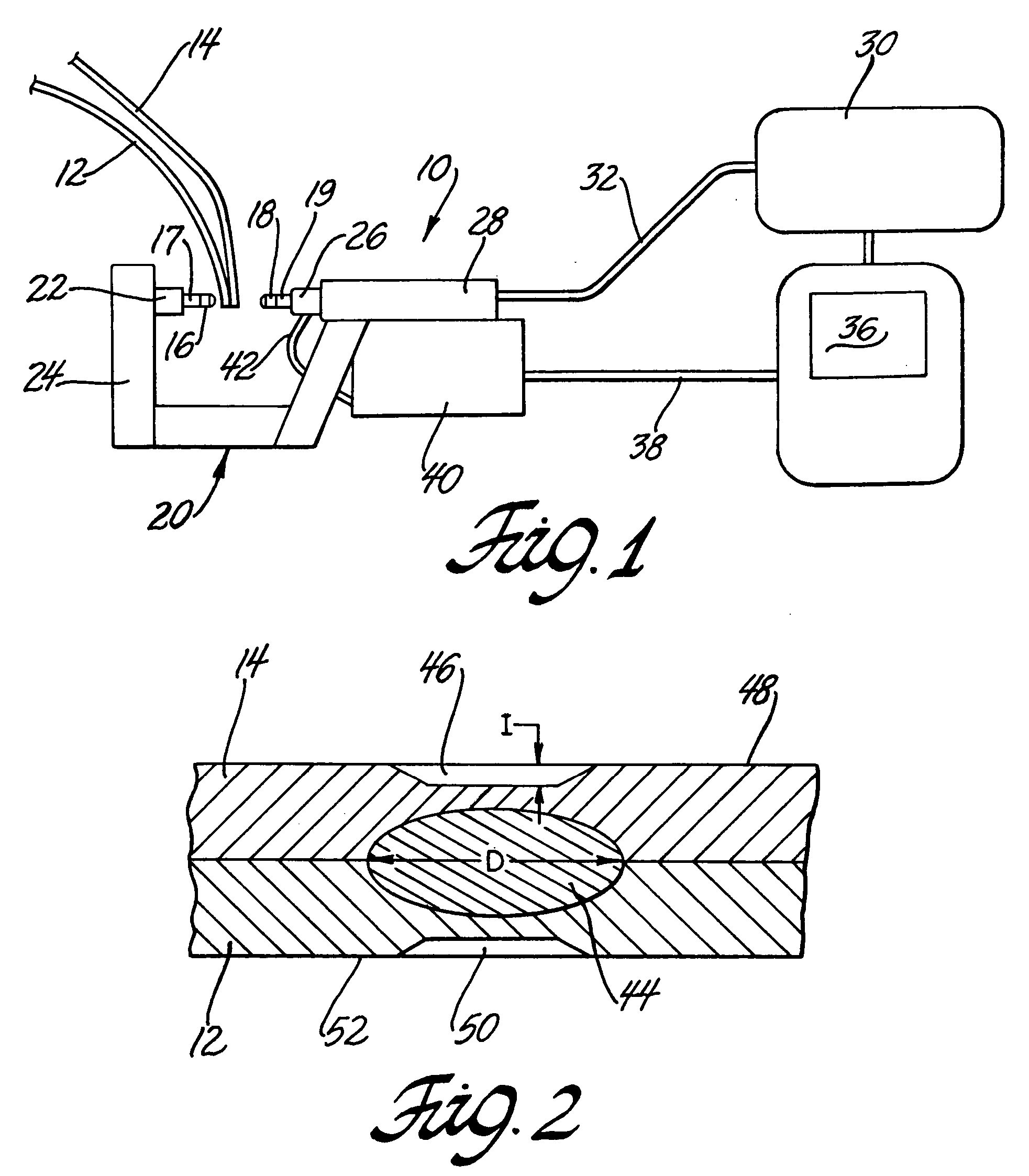
[0008] A suitable weld controller manages the total welding current and its duration. The force applied by the weld electrode is also managed by the weld controller and measured by a suitable load cell placed between the movable electrode and the holder into which it is inserted. The indentation in the workpiece surface is suitably measured by the displacement (i.e., the advancement) of the movable electrode as it applies an electrode force and welding current is passed through the weld site of the workpiece. Electrode displacement during welding is usually relatively small, typically a fraction of a millimeter, and is to be accurately measured. Accordingly, the subject process is best performed using a welding gun in which the movable electrode is advanced using a servomotor. The movement of the electrode in displacing weld material is accurately determined from precise measurement of the rotation of the servomotor that drives the electrode.
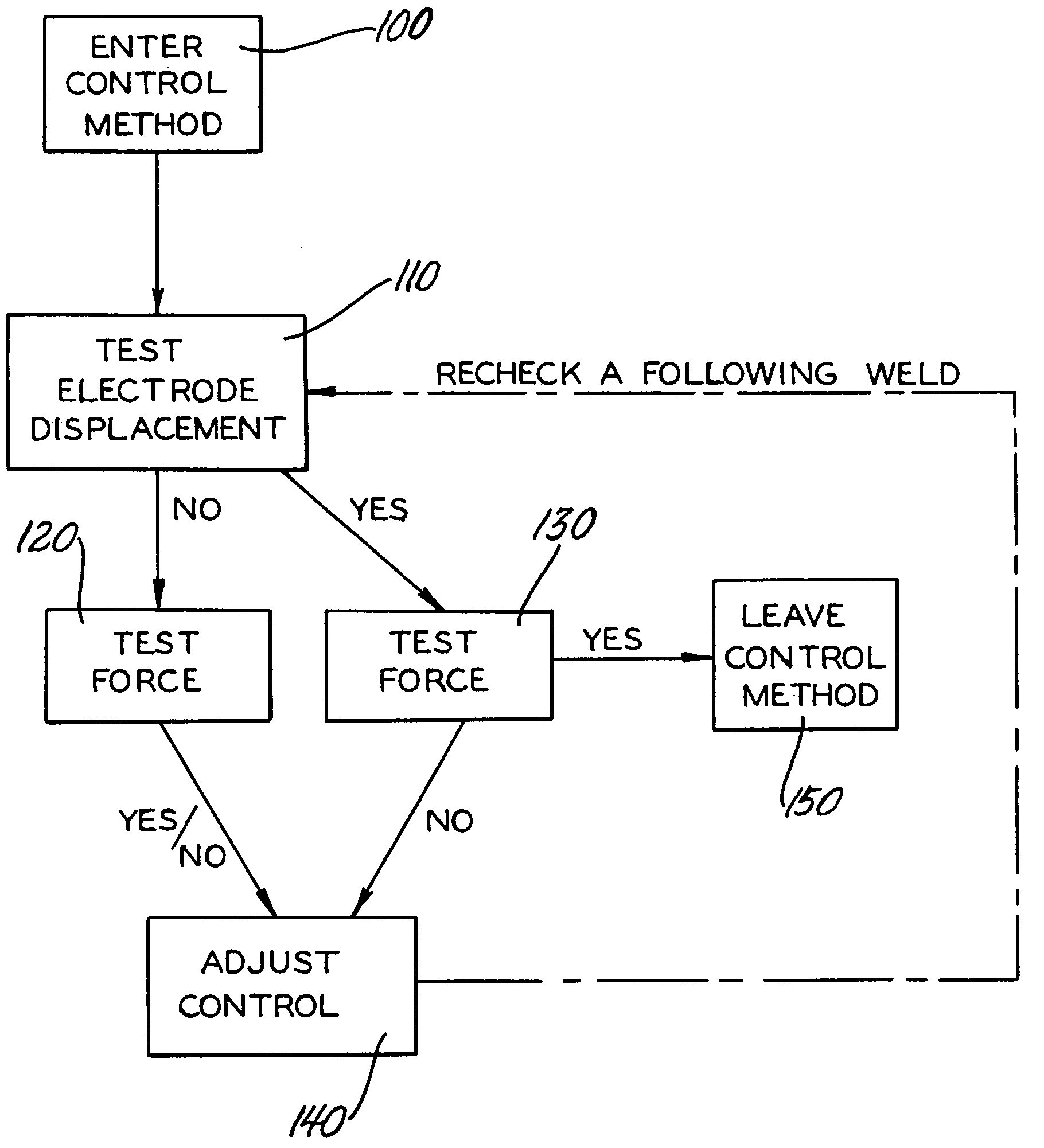
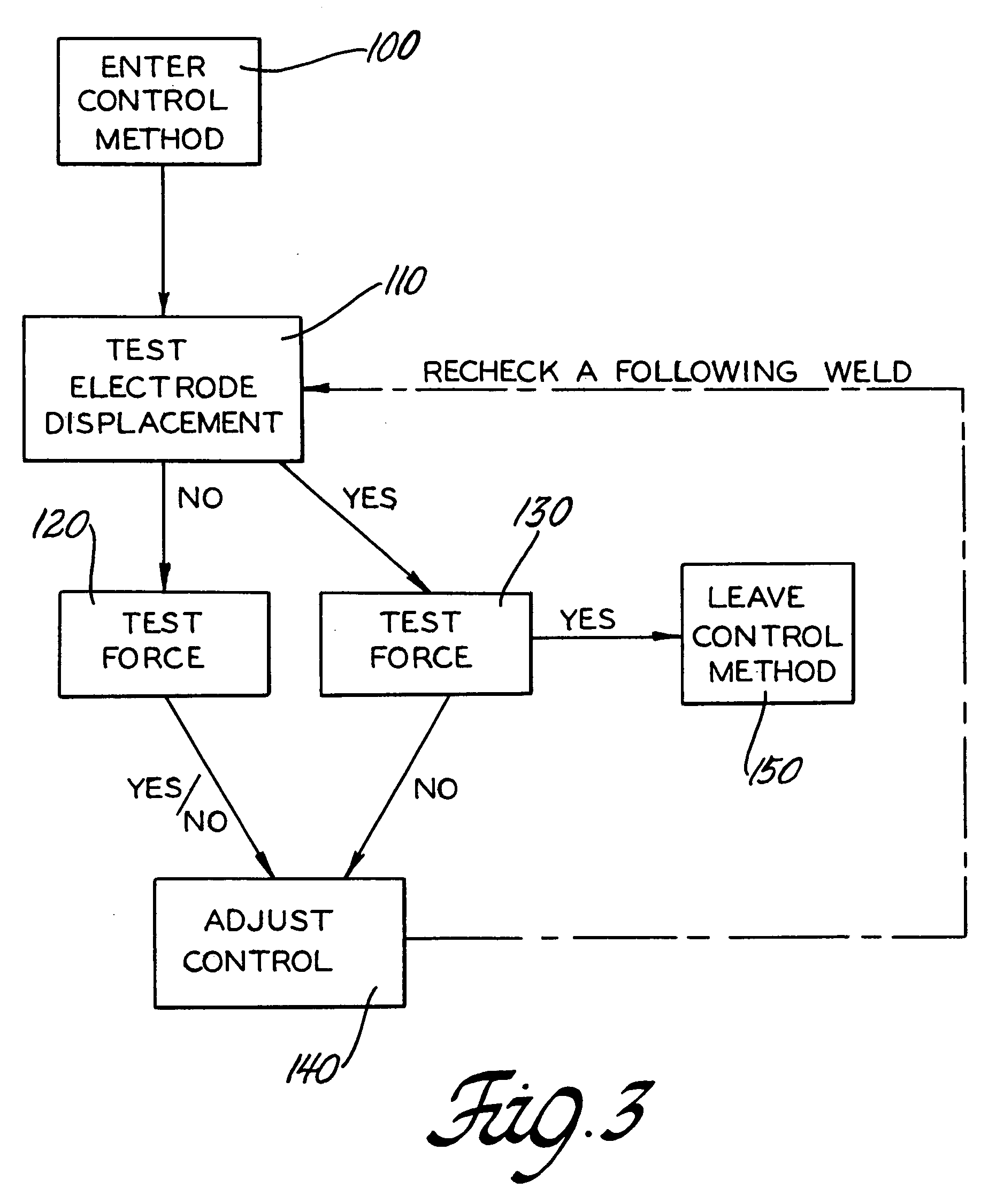
[0011] This method of monitoring servo movable electrode displacement and load cell force values enables spot welding operations to proceed while producing suitable weld nuggets of substantially uniform size. The process is continually ongoing so that only small corrections are required and the overall welding operation is stabilized. Furthermore, the control method is easily performed by the welding controller without interrupting welding operations. Welding operations are stopped only when adjustment of the weld current does not work to correct the electrode displacement and force values. This method has proven to be very useful and successful in maintaining spot weld nugget quality in a long sequence of spot welding operations.

Problems solved by technology

But variations creep into the operation because of electrode wear and workpiece gap and orientation.

Method used


Image

  • Resistance welding control method
  • Resistance welding control method
  • Resistance welding control method

Examples


Embodiment Construction

[0016] The present invention provides a method of controlling welding parameters while producing a series of substantially uniform spot welds in a workpiece and / or a series of workpieces. It is found that weld nugget size in a series of spot welds can be reliably controlled by monitoring the electrode displacement and electrode squeeze force during a weld and adjusting the welding current for a succeeding weld in the event that either or both of these parameters fails to suitably match predetermined displacement and force values. A weld nugget of suitable size and quality is produced when both the electrode displacement and the squeeze force values are within suitable ranges.

[0017] During the welding operation the movable electrode is advanced a small amount by the servomotor to apply a predetermined force on the parts. The inward movement (displacement) of the electrode during welding leaves an impression at the site called weld, or surface, indentation. After the current is stopp...


PUM

PropertyMeasurementUnit
total currentaaaaaaaaaa
thicknessesaaaaaaaaaa

Abstract

This invention provides a method of producing a series of substantially uniform spot welds between two metal parts using a servomotor driven movable electrode and an axially opposing fixed electrode. Target values for electrode displacement in producing a weld indentation and electrode squeeze force are determined for the electrodes and workpieces. During welding operations electrode displacement and electrode force measurements are continually taken and compared with the displacement and force target values. While the measured values are within a tolerance range of the target values, welding is continued using the preset parameters. When either or both of the measured electrode displacement or force value falls outside the target range the total welding current is adjusted in small increments to correct the displacement and / or force values and, thereafter, welding is continued using the new total welding current.

Description

TECHNICAL FIELD [0001] This invention relates generally to electrical resistance spot welding of sheet metal assemblies and, more specifically, to a control method of producing a sequence of spot welds of substantially uniform weld size and quality. BACKGROUND OF THE INVENTION [0002] The construction of automotive bodies and other manufacturing operations often requires the formation of many uniformly sized electrical resistance spot welds. The welds (or weld nuggets) are made by bringing one or more assemblies of sheet metal parts to a welding station where a computer controlled robot, or other welding machine(s), systematically and sequentially forms a series of spot welds to attach the parts of the assembly or assemblies into integral bodies. [0003] The welding is performed using a weld gun typically having copper or copper alloy welding electrodes (i.e., a fixed electrode and a movable electrode). The electrodes are axially aligned in opposition to each other. They are positione...

Claims


Application Information

Patent Timeline
Patent Type & Authority Applications(United States)
IPC IPC(8): B23K11/11B23K11/25
CPCB23K11/11B23K11/253B23K31/125B23K11/311B23K11/255
Inventor WANG, PEI-CHUNGTHORNTON, ROBERT T.SCHMIDT, KENNETH R.MARIN, SAMUEL PAUL
Owner GM GLOBAL TECH OPERATIONS LLC
Learn More