System and method for clamp current regulation in field-weakening operation of permanent magnet (PM) machines

a technology of permanent magnet machines and clamp current, which is applied in the field of system and method of clamp current regulation in the field of fieldweakening operation of permanent magnet machines, can solve the problems of excessive voltage application to the inverter, undesirable addition of incremental costs to the drive system, and reducing the effective electromotive force seen by the inverter, so as to achieve the maximum possible torque and maximize machine efficiency

Active Publication Date: 2005-03-03
DELPHI TECH IP LTD
View PDF19 Cites 70 Cited by
  • Summary
  • Abstract
  • Description
  • Claims
  • Application Information

AI Technical Summary

Benefits of technology

[0011] The invention detects when the output of a current regulator exceeds the available voltage vector, and in response thereto, provides for clamping the proportional-integral (PI) current regulators at the available voltage vector. Through the foregoing, the invention ensures that the current regulator does not run out of voltage, maximizes machine efficiency, and provides a maximum possible torque in the field-weakening region. It is important to note that the base speed point may change significantly depending on DC-link voltage variations and on rotor temperature, which can change the magnetic characteristics of the machine. Nonetheless, a controller in accordance with the present invention is able to properly adjust to the variable base speed.
[0012] A device in accordance with the present invention is provided to regulate current provided to a permanent magnet (PM) machine. The device includes a processing and drive circuit, and a current regulator. The current regulator includes a command circuit, a control circuit, and a limiter. The processing and drive circuit is responsive to a direct voltage command signal (Vds) and a quadrature voltage command signal (Vqs) configured to produce a plurality of phase current signals for input to the PM machine. The command circuit is responsive to a current input command signal. The command circuit is configured to produce a direct current error signal and a quadrature current error signal. The control circuit is responsive to the direct and quadrature current error signals and is configured to produce the direct and quadrature voltage command signals. Finally, in accordance with the present invention, the limiter is configured to limit the direct and quadrature voltage command signals to respective preselected levels.
[0013] Other features, objects and advantages of the present invention will become apparent to one of ordinary skill in the art from the description that follows and may be realized by means of the instrumentalities and combinations particularly pointed out in the appended claims, taken in conjunction with the accompanying drawings.

Problems solved by technology

This would undesirably add incremental costs to the drive system.
The flux created by this current is in opposition to the rotor flux, and thus reduces the effective electromotive force seen by the inverter.
Failure to control the current to an appropriate value will likely result in the application of excessive voltage to the inverter, which is undesirable.
However, the use of look-up tables requires the creation of numerous and cumbersome data structures within the look-up tables themselves to handle all possible situations in the system and its environment.
Another disadvantage, however, of this approach is that if the magnetic characteristics of the PM machine change due to rotor temperature variations and / or the DC-link voltage change, the look-up table or function may no longer be valid.
This may cause the current regulator to exceed the voltage limit, which results in the loss of machine control, which is undesirable.

Method used


Image

  • System and method for clamp current regulation in field-weakening operation of permanent magnet (PM) machines
  • System and method for clamp current regulation in field-weakening operation of permanent magnet (PM) machines
  • System and method for clamp current regulation in field-weakening operation of permanent magnet (PM) machines

Examples


Embodiment Construction

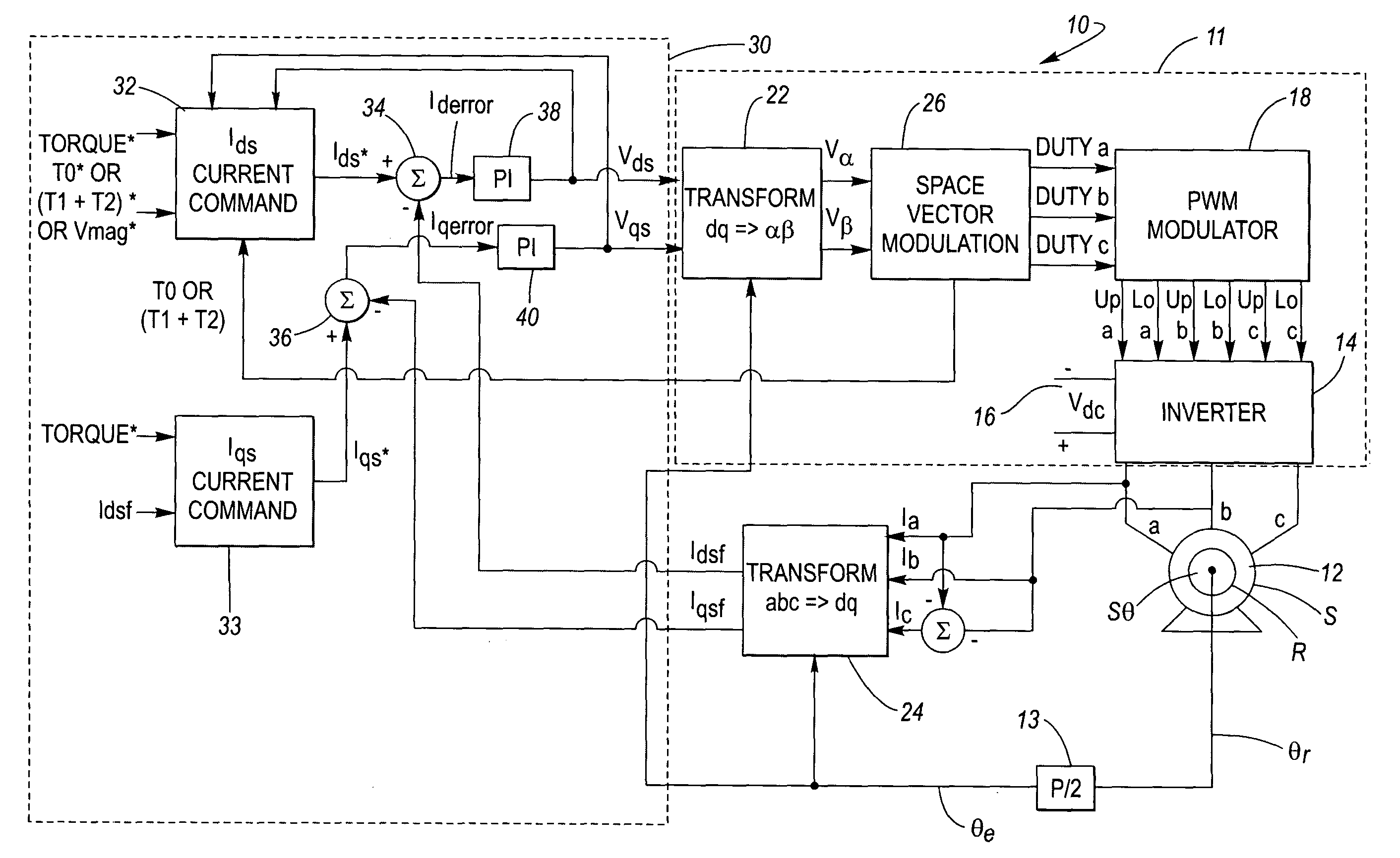
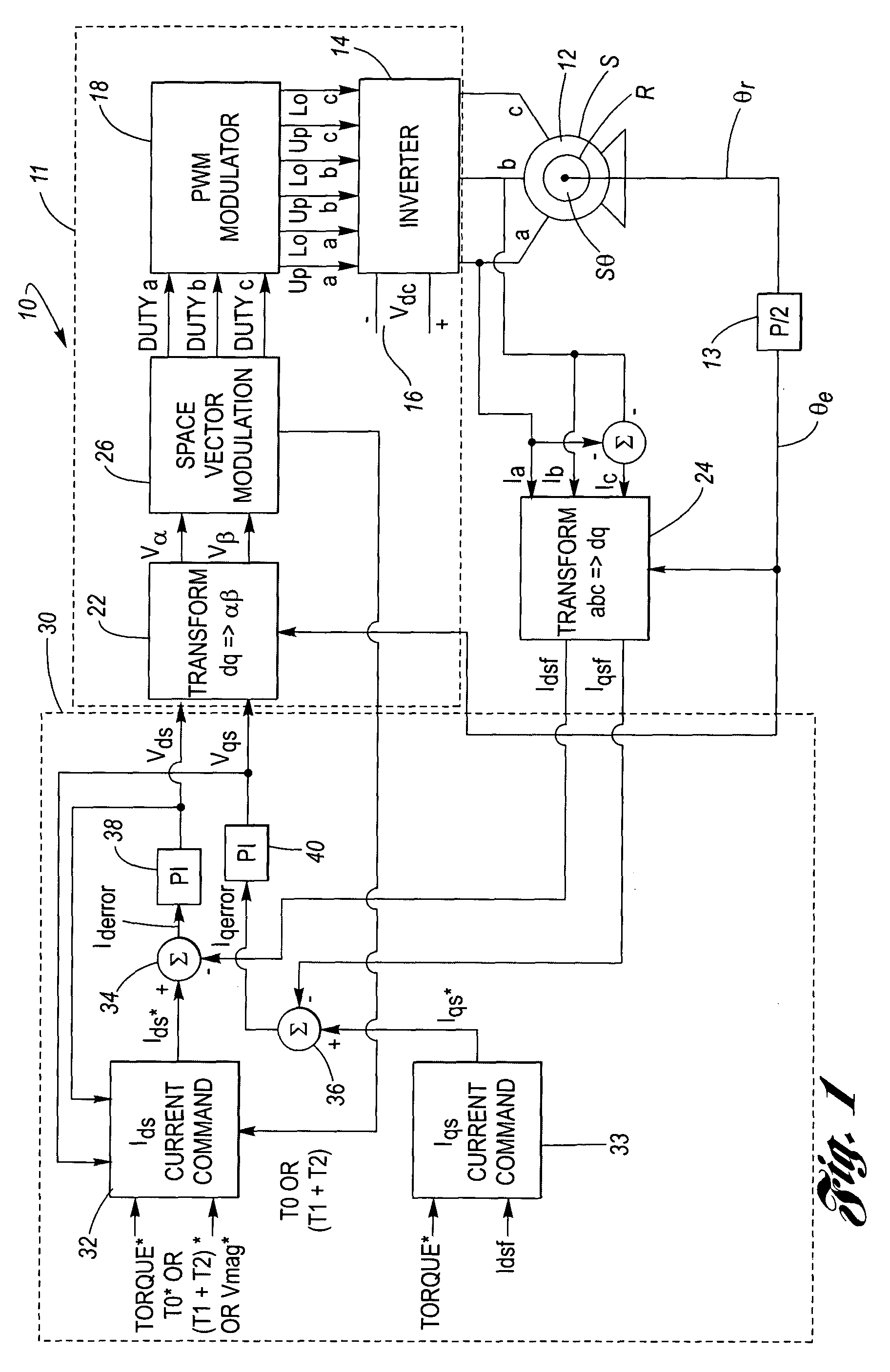
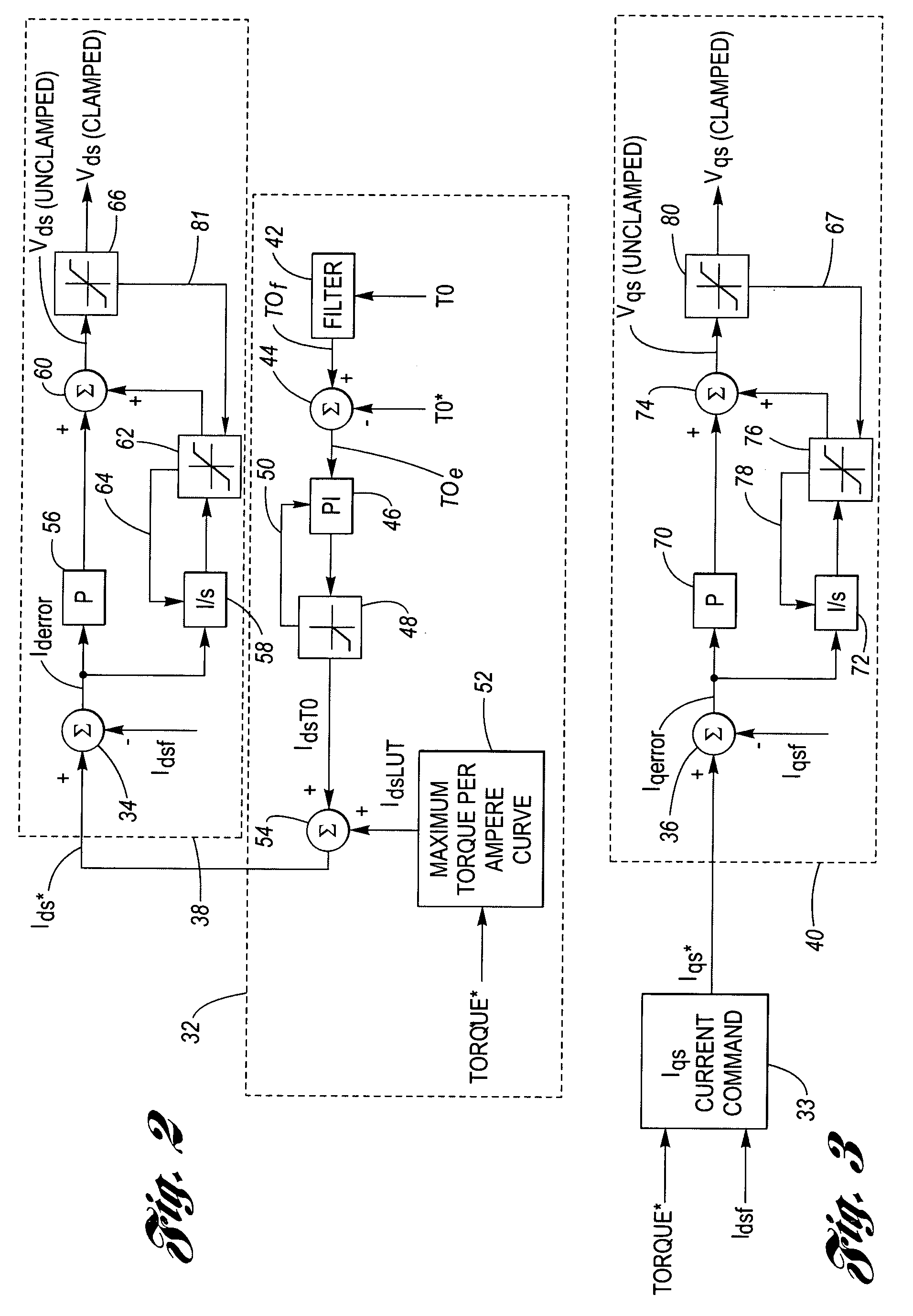
[0018] The invention is directed to a method and apparatus for current control in permanent magnet (PM) machines. The method is configured to produce additional functionality in the field-weakening region.

[0019] To extend the operational speed range of permanent magnet (PM) machines, it is necessary to de-flux the machine by applying additional negative current in the synchronous D-axis, Ids. The advantage of the method is that it applies the appropriate amount of current at each operating point across the entire speed range of the machine, that is, in the constant torque region and in the field-weakening region.

[0020] An important feature of the invention is that when an output of a current regulator would otherwise exceed the available voltage, the limiter of the invention clamps the voltage vector.

[0021] It is important to note that the base-speed point of a PM machine may change significantly depending upon variations in rotor temperature and the DC-link voltage. However, the...


PUM


Abstract

A device to regulate current produced by a permanent magnet machine responsive to a plurality of phase current signals. The motor produces torque for application on a shaft. A processing and drive circuit responsive to a direct current command signal and a quadrature current command signal produces phase current signals for input to the motor. A command circuit responsive to the phase current signals, an angular position of said shaft, and a voltage input command signal to produce a direct current error signal and a quadrature current error signal. A control circuit responsive to the direct and quadrature current error signals produces the direct voltage signal command and the quadrature voltage signal command. The control circuit has a direct and quadrature proportional gain, integrator and clamp circuits. An algorithm produces limited or clamped voltage modulation index signals to obtain maximum efficiency and maximum torque per ampere in the speed range. The algorithm ensures that the current regulator does not run out of voltage by limiting the voltage vector to the achievable voltage vector range that provides maximum torque per ampere and maximum efficiency.

Description

BACKGROUND OF THE INVENTION [0001] 1. Technical Field [0002] The present invention is directed generally to electromechanical machines, and, in particular, to a system and a method for current regulation in the field-weakening operation of permanent magnetic (PM) machines. [0003] 2. Description of the Related Art [0004] In the control of inverter-driven permanent magnet (PM) machines, field-weakening is often used to lower the inverter voltage rating for a given application. That is, without field-weakening the inverter manufacturer would have to use components rated to handle higher levels of voltage for that given application. This would undesirably add incremental costs to the drive system. Field-weakening may be accomplished by configuring the machine windings to provide a greater torque per amp ratio, and thus achieve a lower base speed for a given torque load. During high speed operation, the phase current may be applied to the machine windings in advance of the phase electrom...

Claims


Application Information

Patent Timeline
Patent Type & Authority Applications(United States)
IPC IPC(8): H02P7/00H02P21/06
CPCH02P21/06
Inventor GALLEGOS-LOPEZ, GABRIELGUNAWAN, FANI S.WALTERS, JAMES E.
Owner DELPHI TECH IP LTD
Why Eureka
Try Eureka