Lithographic apparatus and device manufacturing method

a technology of lithographic apparatus and manufacturing method, which is applied in the direction of liquid spraying apparatus, electric devices, special surfaces, etc., can solve problems such as positioning errors, achieve low solubility, reduce the amount of gas dissolved, and maintain the overpressure constant

Inactive Publication Date: 2005-03-03
ASML NETHERLANDS BV
View PDF99 Cites 286 Cited by
  • Summary
  • Abstract
  • Description
  • Claims
  • Application Information

AI Technical Summary

Benefits of technology

In case it is inconvenient to locate the tank at the necessary height relative to the immersion head, an overpressure of gas may be provided in the tank above the immersion liquid. In such an embodiment, the pressure at the flow restriction is determined by the sum of the overpressure and the head pressure. This may even allow the tank to be located below the flow restrictor so that there is a negative head. Of course if an overpressure is used, it should be maintained sufficiently constant so that the pressure at the flow restriction is within the permissible range of variation, however that should be readily achieved with commercially available pressure regulators. A constant flow of gas through the tank may also assist in maintaining the overpressu

Problems solved by technology

Even small pressure fluctuations, such as may occur if the immersion liquid is pumped to the liquid supply system,

Method used


Image

  • Lithographic apparatus and device manufacturing method
  • Lithographic apparatus and device manufacturing method
  • Lithographic apparatus and device manufacturing method

Examples


Embodiment Construction

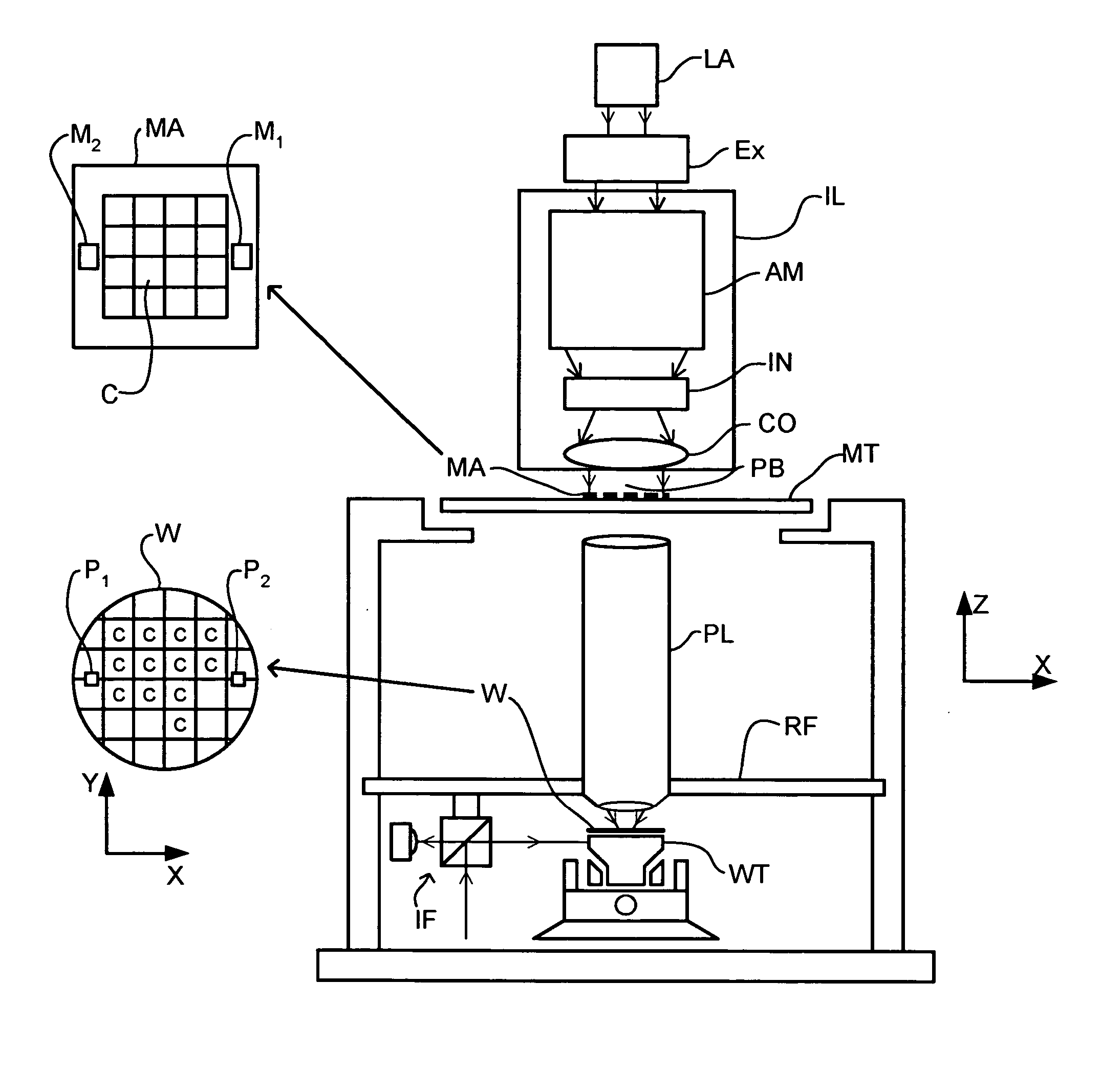
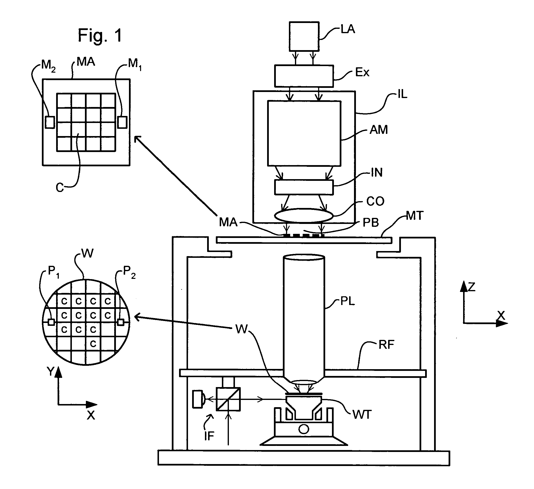
FIG. 1 schematically depicts a lithographic apparatus according to one embodiment of the invention. The apparatus comprises: an illumination system (illuminator) IL configured to condition a radiation beam PB (e.g. UV radiation or DUV radiation). a support structure (e.g. a mask table) MT constructed to support a patterning device (e.g. a mask) MA and connected to a first positioner configured to accurately position the patterning device in accordance with certain parameters; a substrate table (e.g. a wafer table) WT constructed to hold a substrate (e.g. a resist-coated wafer) W and connected to a second positioner configured to accurately position the substrate in accordance with certain parameters; and a projection system (e.g. a refractive projection lens system) PL configured to project a pattern imparted to the radiation beam PB by patterning device MA onto a target portion C (e.g. comprising one or more dies) of the substrate W.

The illumination system may include various...


PUM

PropertyMeasurementUnit
Timeaaaaaaaaaa
Heightaaaaaaaaaa
Heightaaaaaaaaaa

Abstract

In an immersion lithography apparatus, the immersion liquid is supplied from a tank via a flow restrictor. The liquid held in the tank is maintained at a substantially constant height above the flow restrictor to ensure a constant flow of liquid.

Description

This application claims priority from European patent application EP 03254812.5, filed Jul. 31, 2003, which is incorporated herein in its entirety. FIELD The present invention relates to a lithographic apparatus and a method for manufacturing a device. BACKGROUND A lithographic apparatus is a machine that applies a desired pattern onto a substrate, usually onto a target portion of the substrate. A lithographic apparatus can be used, for example, in the manufacture of integrated circuits (ICs). In that instance, a patterning device, which is alternatively referred to as a mask or a reticle, may be used to generate a circuit pattern to be formed on an individual layer of the IC. This pattern can be transferred onto a target portion (e.g. comprising part of, one, or several dies) on a substrate (e.g. a silicon wafer). Transfer of the pattern is typically via imaging onto a layer of radiation-sensitive material (resist) provided on the substrate. In general, a single substrate will c...

Claims


Application Information

Patent Timeline
IPC IPC(8): G03F7/20H01L21/027
CPCG03F7/70341
Inventor MERTENS, JEROEN JOHANNES SOPHIA MARIAHOOGENDAM, CHRISTIAAN ALEXANDERJANSEN, HANSTINNEMANS, PATRICIUS ALOYSIUS JACOBUSVAN DEN SCHOOR, LEON JOSEPH MARIADONDERS, SJOERD NICOLAAS LAMBERTUSSTREEFKERK, BOB
Owner ASML NETHERLANDS BV
Why Eureka
Try Eureka