Stent delivery catheter

a stent and catheter technology, applied in the direction of tubular organ implants, ear treatment, blood vessels, etc., can solve the problems that the doctor may not be able to push the stent through a constriction in the duct, and achieve the effect of facilitating the stent's entry into the biliary tra

Inactive Publication Date: 2005-03-03
CR BARD INC
View PDF31 Cites 15 Cited by
  • Summary
  • Abstract
  • Description
  • Claims
  • Application Information

AI Technical Summary

Benefits of technology

[0005] The stent is formed from a tube of relatively stiff thermoplastic polymer to include ridges and valleys along its outer surface. The ridges and valleys may be helical and may form a thread-like configuration. The ridges and valleys are formed by thermoplastic deformation of the outer surface of the tube. The dimensions of the ridges and valleys can be varied to provide stents with different characteristics. The proximal and distal ends of the stent are preferably not provided with valleys or ridges. The distal end may be tapered to facilitate its entry into the biliary tract. Additionally, the distal end of the stent, which will serve as an inlet for biliary liquids, may have an elongate shape to provide a wider mouth for entry of such liquids. The device may be placed by pushing it to the desired location in the biliary tree, as is presently done, or in accordance with the invention, the stent can be rotated so that the helical ridges and valleys can serve as threads to advance the stent through a biliary stricture. The ridges engage the walls of the duct to secure the stent in place.

Problems solved by technology

Also among the difficulties with prior polymeric stents is that in some cases the physician may not be able to push the stent through a constriction in the duct.

Method used


Image

  • Stent delivery catheter
  • Stent delivery catheter
  • Stent delivery catheter

Examples


Embodiment Construction

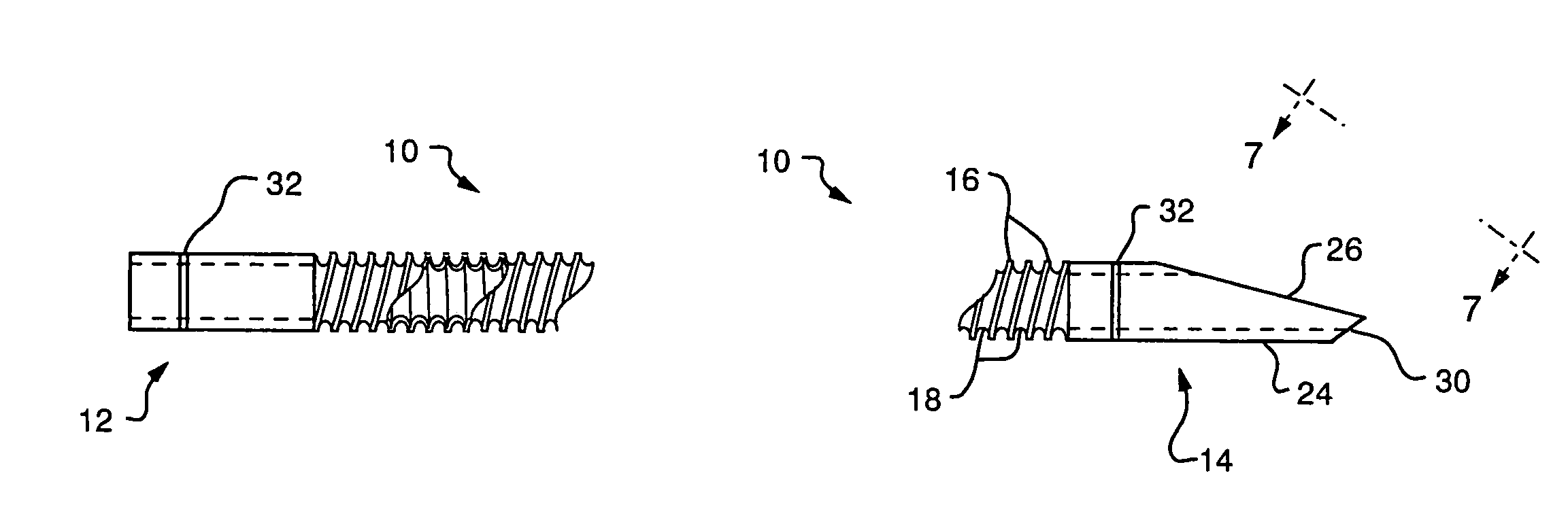
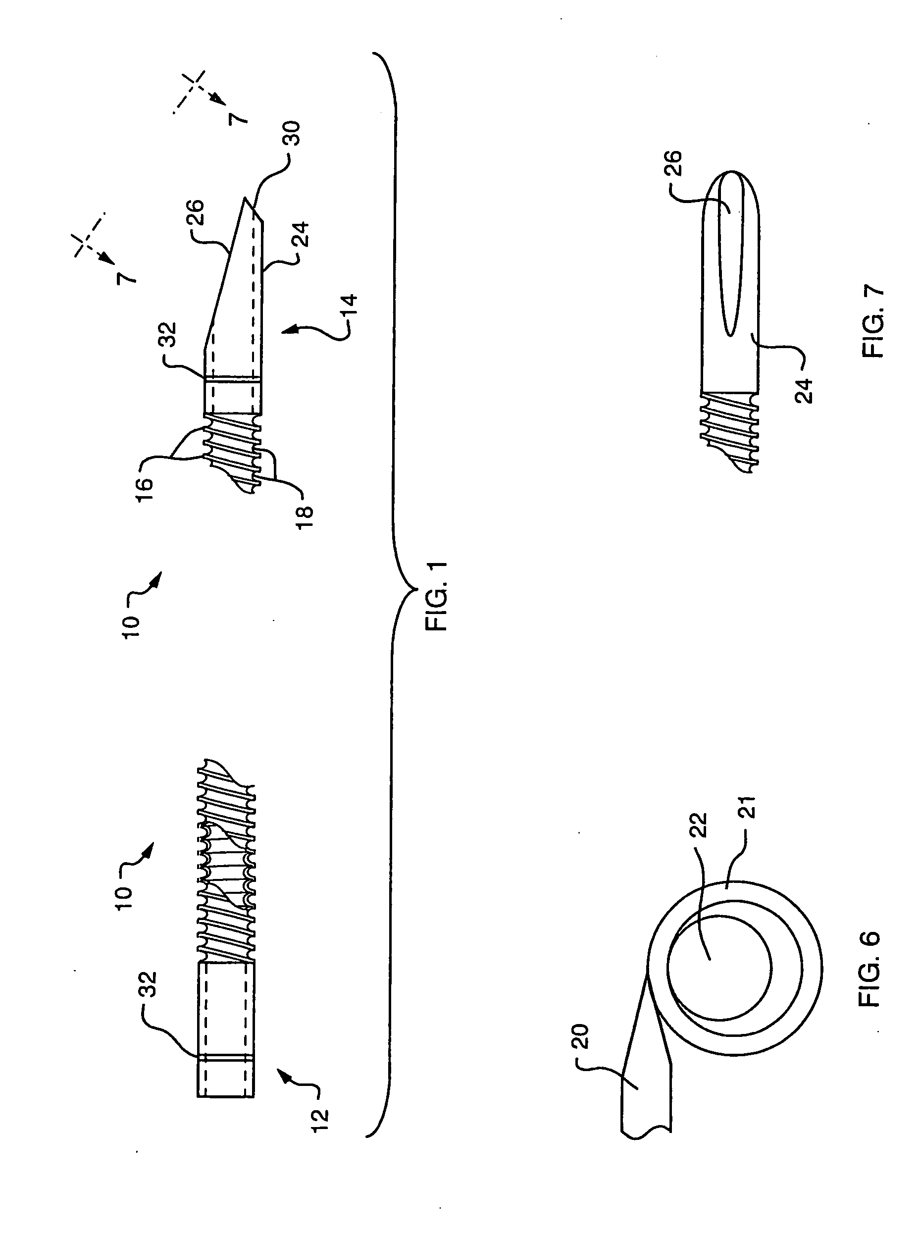
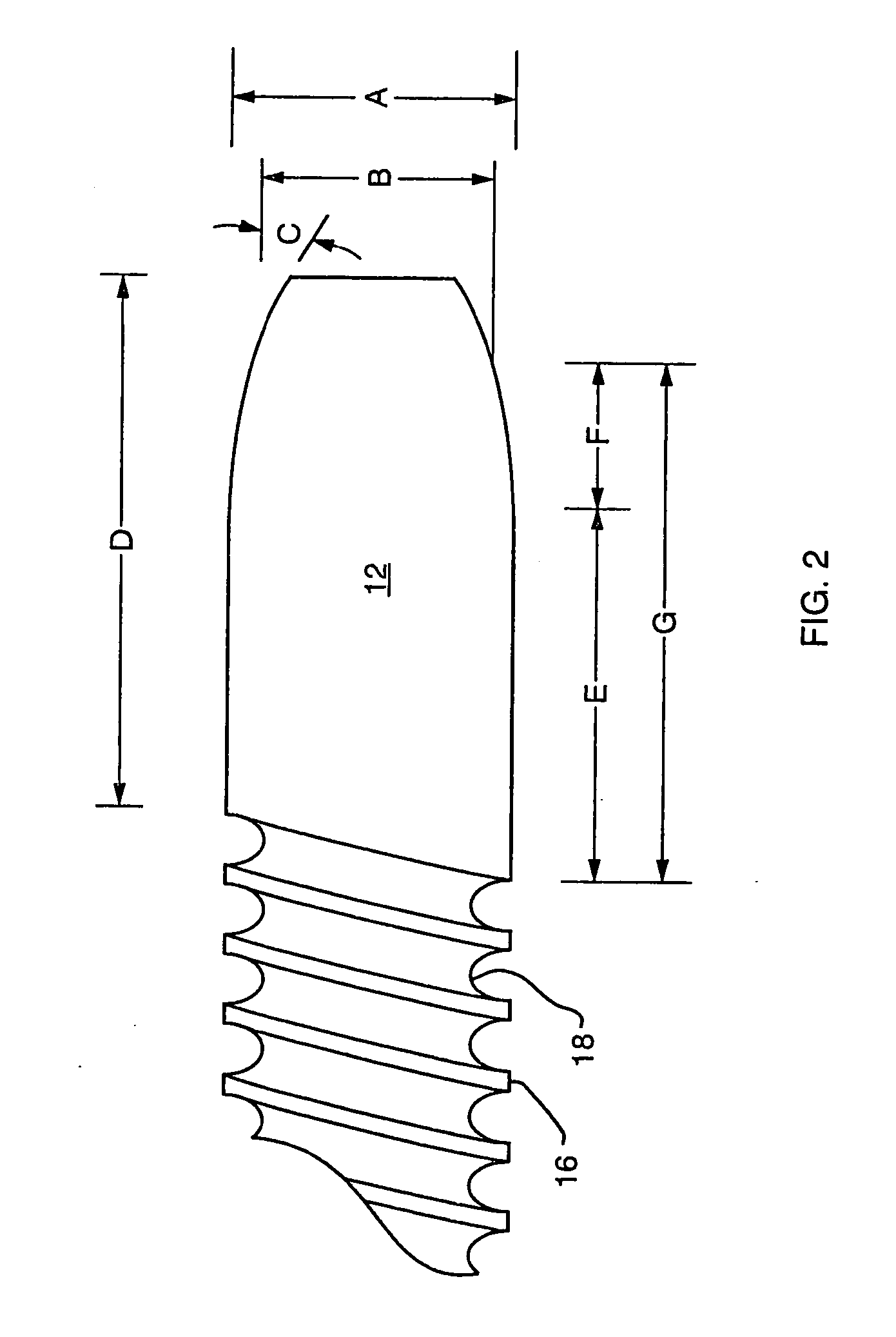
[0021]FIG. 1 illustrates, in side view, an embodiment of a stent 10 having a proximal end 12 and a distal end 14. The stent is formed from a tube of a polymer, commercially available from Victrex under the trade designation PEEK. The polymer is a polyetheretherketone, a linear aromatic semi-crystalline polymer. By way of example, for use as a biliary stent, the PEEK tubing may be of the order of 4 to 15 centimeters long having an outer diameter of between about 5 to 11 French (0.065 inches to 0.143 inches). The wall thickness of the tubing may be of the order of about 0.005 inches. The PEEK material is thermoplastic and is formed from its extruded tubular configuration to that illustrated in FIG. 1 in which at least a portion of the length of the tube defines circumferentially extending external ridges 16 alternating with valleys 18. Preferably the ridges are formed in a helical, thread-like pattern.

[0022] The ridges 16 and valleys 18 are formed by applying a heated tool against th...


PUM


Abstract

A delivery device for a biliary stent constructed of thermoplastic material with ridges and valleys formed along the outer surface of the stent that provide a helical, thread-like configuration. The delivery device comprises an external surface that is selectively expandable to engage an interior surface of the tubular stent. Additionally the exterior surface may include ridges and valleys that coincide with ridges and valleys defined by the helical thread extending through the stent in order to provide a more secure engagement with the stent during delivery.

Description

RELATED DISCLOSURE INFORMATION [0001] This application claims the benefit of U.S. Provisional Application No. 60 / 478,050, filed on Jun. 12, 2003, the subject matter of which is related to the disclosure document filed at the U.S. Patent and Trademark Office on Jun. 12, 2001, and assigned Disclosure Document No. 495220. The entire teachings of the application and disclosure are incorporated herein by reference.FIELD OF THE INVENTION [0002] This invention relates to stents and stent delivery devices and, in particular, to devices adapted for use in the biliary tract. [0003] Biliary stents, for many years, have been made in the form of a polymer tube that can be advanced on a delivery catheter through an endoscope and into the bile duct where it is deployed. The tubular stent is selected to be sufficiently strong to resist collapse to maintain an open lumen through which digestive liquids can flow into the digestive tract. Among the desirable features of such a stent is that it be long...

Claims


Application Information

Patent Timeline
Patent Type & Authority Applications(United States)
IPC IPC(8): A61F2/04A61F2/94A61F11/00A61M
CPCA61F2/07A61F2/94A61F2002/9505A61F2002/041A61F2/95
Inventor AZNOIAN, HAROLD M.WEISER, MICHAEL F.
Owner CR BARD INC
Why Eureka
Try Eureka