Variable frequency PWM controller circuit

Active Publication Date: 2005-03-10
DELTA ELECTRONICS INC
View PDF6 Cites 38 Cited by
  • Summary
  • Abstract
  • Description
  • Claims
  • Application Information

AI Technical Summary

Benefits of technology

[0010] A new PWM signal generating scheme is presented, as shown in FIG. 4. The on time and the off time of the PWM signal are regulated simultaneously according to the scheme. Each of the generated PWM signals will have relatively a very short on time and

Problems solved by technology

Meanwhile, the control circuit dissipates relatively low loss due to relatively low frequency operation.
In the standby operation mode, the power circuit always operates with relatively a very short time Ton,sb and thus a very small duty cycle, but the switching frequency is still high as normal operation, resulting in relatively much switching loss and driving loss of the main switch and much power loss of the controller which are the major parts of the standby loss.
Therefore, the standby loss of the converter will be

Method used


Image

  • Variable frequency PWM controller circuit
  • Variable frequency PWM controller circuit
  • Variable frequency PWM controller circuit

Examples


Embodiment Construction

[0025] Although this invention is susceptible to embodiments of many different forms, a preferred embodiment will be described and illustrated in detail herein. The present disclosure exemplifies the principle of the invention and is not being considered a limitation to the broader aspects of the invention to the particular embodiment as described.

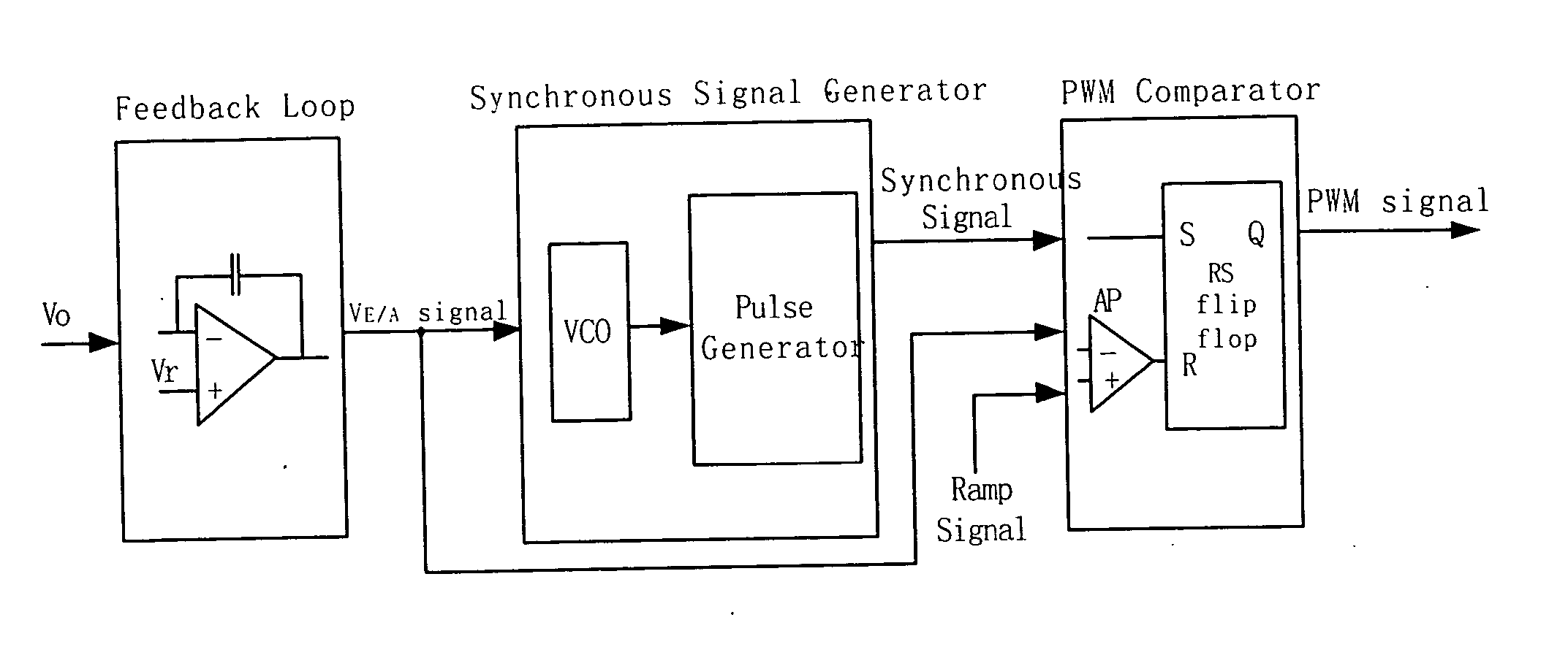
[0026] In FIG. 5, a circuit diagram to realize the VF PWM control scheme according to the present invention is shown. The overall circuit of the invention has three parts including a feedback loop, a synchronous signal generator and a PWM comparator.

[0027] The output voltage is input to the feedback loop which in-turn outputs an error-amplified voltage VE / A. The VE / A signal is firstly input to a synchronous signal generator, which includes a VCO (Voltage Control Oscillator) and selectively includes a pulse generator, which is an optional component coupled to the VCO and can be omitted without damping the functions of the synchronous gene...


PUM


Abstract

The present invention discloses a circuit that generates a variable frequency pulse width modulation (VF PWM) signal. Different from the conventional PWM controller, the frequency and duty cycle of the output PWM signal vary with the error-amplified voltage of the feedback loop simultaneously in this invention. The higher the error-amplified voltage of the feedback loop is, the lower the duty cycle with lower frequency will be. A very low duty cycle PWM signal can be generated stably while its frequency is very low.

Description

FIELD OF THE INVENTION [0001] The present invention relates to switching mode power supplies, and more specifically to a varied frequency pulse width modulation controller for low standby loss solution. BACKGROUND OF THE INVENTION [0002] The trend in the design of switching mode power supplies has been toward relatively low power loss, low ripple and low noise under light load condition, especially for those widely used adaptors for notebooks, computers, and chargers for mobile telecommunication apparatus. This kind of power supplies frequently operates under a light or zero load condition, which is named as the standby operation mode. [0003] A flyback converter is the most commonly used topology for this application with pulse width modulation (PWM) control for the output regulation. To achieve relatively very low power loss under light or open load condition, it is the key factor to control the power stage to operate at a relatively very low switching frequency to decrease the swi...

Claims


Application Information

Patent Timeline
IPC IPC(8): H02M3/156H03K3/0231
CPCH02M3/156Y02B70/16H03K3/0231H02M2001/0032Y02B70/10H02M1/0032
Inventor GAN, HONGJIANWANG, BOZHANG, ALPHA J.
Owner DELTA ELECTRONICS INC
Why Eureka
Try Eureka