Universal light emitting illumination device and method

a technology of illumination device and light source, which is applied in the direction of coupling device connection, process and machine control, with built-in power, etc., can solve the problems of premature failure, low light output, and high energy waste, and achieve wide operating voltage range, high efficiency, and long life

Active Publication Date: 2005-03-17
LEDVANCE LLC
View PDF42 Cites 128 Cited by
  • Summary
  • Abstract
  • Description
  • Claims
  • Application Information

AI Technical Summary

Benefits of technology

[0009] The disclosed embodiments offer the advantage of providing a universal LED light bulb module with long life and high efficiency at a wide operating voltage range with a very small size allowing for the incorporation within the envelope and form of existing lightbulb bases. The LED illumination module has the further advantage over conventional incandescent type bulbs by providing a precise wavelength output envelope, resulting in high efficiency

Problems solved by technology

The radiation that is emitted by hot filaments is spread over a wide spectral range and much of the energy is wasted owing to emission outside the visible range.
Moreover, such filaments must be designed for the specific voltage of operation, e.g., a bulb designed for 2.7 volt (V) operation cannot be used for operation at a higher, 3.6 V level without causing immediate premature failure.
Similarly, operating at a lower voltage, such as 2.2 V lowers the light output to unaccep

Method used


Image

  • Universal light emitting illumination device and method
  • Universal light emitting illumination device and method
  • Universal light emitting illumination device and method

Examples


Embodiment Construction

[0019] While this invention is susceptible to embodiment in many different forms, there are shown in the drawings and will be described herein in detail specific embodiments thereof with the understanding that the present disclosure is to be considered as an example of the principles of the invention and is not to be limited to the specific embodiments described.

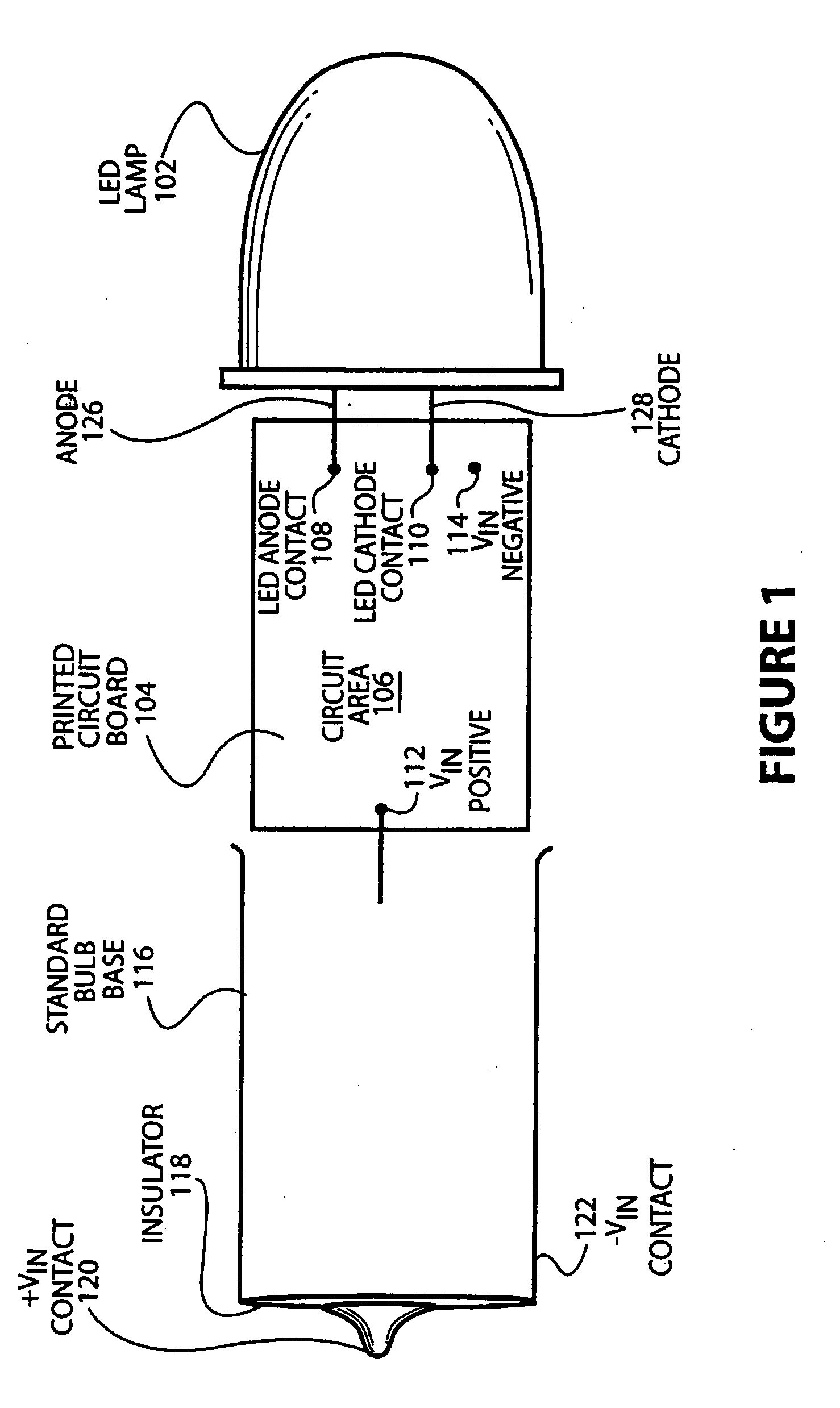
[0020]FIG. 1 is a drawing showing a typical embodiment of a universal LED illumination device to retrofit an incandescent lightbulb application. As illustrated in FIG. 1, an LED illumination device 100 may be made up of an LED lamp 102 that is connected to a printed circuit board 104 by an anode 126 wire at an LED anode connect 108 and a cathode 128 wire and an LED cathode connect 110 located on the printed circuit board 104. This printed circuit board 104 contains electronic circuitry placed in circuit area 106 and is of small size enabling the printed circuit board 104 to fit within the envelope of a standard bulb base 11...


PUM


Abstract

Disclosed is a method and apparatus for providing a light emitting diode and driving circuitry integrated into a component module that will retrofit common incandescent lightbulb applications. The disclosed embodiments will perform with high efficiency at a wide operating voltage range with a very small size allowing for the incorporation within the envelope and form of existing lightbulb bases. Therefore, a single universal LED light bulb module can be used to replace the dozens of conventional LED and incandescent lights currently being used. The electronic circuitries used to drive the LEDs are extremely compact and consequently can be incorporated in nearly any standard bulb base.

Description

CROSS-REFERENCE TO RELATED APPLICATION [0001] This non-provisional patent application claims benefit to provisional application 60 / 502,495 filed Sep. 12, 2003. FIELD OF THE INVENTION [0002] The present invention relates to a light emitting diode illumination device and method and more specifically to a light emitting diode and driving circuitry integrated into a component module that will retrofit common incandescent lightbulb applications. BACKGROUND OF THE INVENTION [0003] Currently, lightbulbs for low power lighting applications such as flashlights are dominated by incandescent lights that use hot filaments to provide radiant energy. The radiation that is emitted by hot filaments is spread over a wide spectral range and much of the energy is wasted owing to emission outside the visible range. Moreover, such filaments must be designed for the specific voltage of operation, e.g., a bulb designed for 2.7 volt (V) operation cannot be used for operation at a higher, 3.6 V level withou...

Claims


Application Information

Patent Timeline
IPC IPC(8): F21K99/00
CPCF21Y2101/02Y02B20/383F21K9/135F21V23/003F21K9/17F21S9/02F21K9/137F21K9/232F21K9/233F21K9/27F21Y2115/10F21V23/006F21K9/238Y02B20/30
Inventor CATALANO, ANTHONY
Owner LEDVANCE LLC
Why Eureka
Try Eureka