Coated silver-containing particles, method and apparatus of manufacture, and silver-containing devices made therefrom

a technology of coating and silver, applied in the field of aerosol, can solve the problems of unsuitable commercial particle production, uncontrolled liquid precipitation techniques, and ineffective spray pyrolysis systems, and achieve the effect of carefully controlled particle siz

Inactive Publication Date: 2005-03-24
CABOT CORP
View PDF99 Cites 55 Cited by
  • Summary
  • Abstract
  • Description
  • Claims
  • Application Information

AI Technical Summary

Benefits of technology

The excess carrier gas 238 that is removed in the aerosol concentrator 236 typically includes extremely small droplets that are also removed from the aerosol 108. Preferably, the droplets removed with the excess carrier gas 238 have a weight average size of smaller than about 1.5 microns, and more preferably smaller than about 1 micron and the droplets retained in the concentrated aerosol 240 have an average droplet size of larger than about 2 microns. For example, a virtual impactor sized to treat an aerosol stream having a weight average droplet size of about three microns might be designed to remove with the excess carrier gas 238 most droplets smaller than about 1.5 microns in size. Other designs are also possible. When using the aerosol generator 106 with the present invention, however, the loss of these very small droplets in the aerosol concentrator 236 will typically constitute no more than about 10 percent by weight, and more preferably no more than about 5 percent by weight, of the droplets originally in the aerosol stream that is fed to the concentrator 236. Although the aerosol concentrator 236 is useful in some situations, it is normally not required with the process of the present invention, because the aerosol generator 106 is capable, in most circumstances, of generating an aerosol stream that is sufficiently dense. So long as the aerosol stream coming out of the aerosol generator 102 is sufficiently dense, it is preferred that the aerosol concentrator not be used. It is a significant advantage of the present invention that the aerosol generator 106 normally generates such a dense aerosol stream that the aerosol concentrator 236 is not needed. Therefore, the complexity of operation of the aerosol concentrator 236 and accompanying liquid losses may typically be avoided.
that the aerosol generator 106 normally generates such a dense aerosol stream that the aerosol concentrator 236 is not needed. Therefore, the complexity of operation of the aerosol concentrator 236 and accompanying liquid losses may typically be avoided.
It is important that the aerosol stream (whether it has been concentrated or not) that is fed to the furnace 110 have a high droplet flow rate and high droplet loading as would be required for most industrial applications. With the present invention, the aerosol stream fed to the furnace preferably includes a droplet flow of greater than about 0.5 liters per hour, more preferably greater than about 2 liters per hour, still more preferably greater than about 5 liters per hour, even more preferably greater than about 10 liters per hour, particularly greater than about 50 liters per hour and most preferably greater than about 100 liters per hour; and with the droplet loading being typically greater than about 0.04 milliliters of droplets per liter of carrier gas, preferably greater than about 0.083 milliliters of droplets per liter of carrier gas 104, more preferably greater than about 0.167 milliliters of droplets per liter of carrier gas 104, still more preferably greater than about 0.25 milliliters of droplets per liter of carrier gas 104, particularly greater than about 0.33 milliliters of droplets per liter of carrier gas 104 and most preferably greater than about 0.83 milliliters of droplets per liter of carrier gas 104.
One embodiment of a virtual impactor that could be used as the aerosol concentrator 236 will now be described with reference to FIGS. 26-32. A virtual impactor 246 includes an upstream plate assembly 248 (details shown in FIGS. 27-29) and a downstream plate assembly 250 (details shown in FIGS. 25-32), with a concentrating chamber 262 located between the upstream plate assembly 248 and the downstream plate assembly 250.
Through the upstream plate assembly 248 are a plurality of vertically extending inlet slits 254. The downstream plate assembly 250 includes a plurality of vertically extending exit slits 256 that are In alignment with the inlet slits 254. The exit slits 256 are, however, slightly wider than the inlet slits 254. The downstream plate assembly 250 also includes flow channels 258 that extend substantially across the width of the entire downstream plate assembly 250, with each flow channel 258 being adjacent to an excess gas withdrawal port 260.
During operation, the aerosol 108 passes through the inlet slits 254 and into the concentrating chamber 262. Excess carrier gas 238 is withdrawn from the concentrating chamber 262 via the excess gas withdrawal ports 260. The withdrawn excess carrier gas 238 then exits via a gas duct port 264. That portion of the aerosol 108 that is not withdrawn through the excess gas withdrawal ports 260 passes through the exit slits 256 and the flow channels 258 to form the concentrated aerosol 240. Those droplets passing across the concentrating chamber 262 and through the exit slits 256 are those droplets of a large enough size to have sufficient momentum to resist being withdrawn with the excess carrier gas 238.

Problems solved by technology

Such liquid precipitation techniques are often difficult to control to produce particles with the desired characteristics.
It is especially difficult by the liquid precipitation route to obtain particles having dense, spherical particle morphology and with good crystallinity.
Spray pyrolysis systems involving silver have, however, been mostly experimental, and unsuitable for commercial particle production.
Also, spray pyrolysis systems are often inefficient in the use of carrier gasses that suspend and carry liquid droplets of the aerosol.

Method used


Image

  • Coated silver-containing particles, method and apparatus of manufacture, and silver-containing devices made therefrom
  • Coated silver-containing particles, method and apparatus of manufacture, and silver-containing devices made therefrom
  • Coated silver-containing particles, method and apparatus of manufacture, and silver-containing devices made therefrom

Examples


example 1

This example demonstrates the preparation of silver-containing particles in which the silver is present in an alloy with palladium.

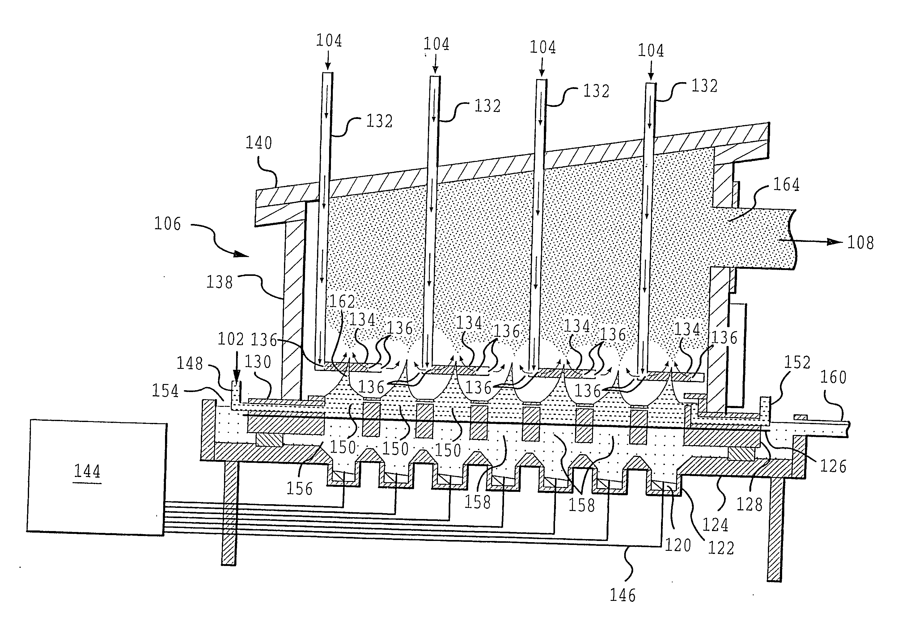
An aqueous solution is prepared including dissolved palladium and silver as nitrates. The total amount of palladium and silver in the solution is 5 weight percent, with the relative proportions of palladium / silver being 70 / 30 on a weight basis, so that, if the silver and the palladium fully alloy, a 70 / 30 Pd / Ag alloy will be obtained in the particles. An aerosol is generated from a single transducer ultrasonic generator operating at a frequency of 1.6 MHz using a carrier gas of nitrogen. Generated aerosols are sent to a furnace to prepare the palladium-containing particles. Reactor temperatures are varied from 900° C. to 1400° C. The samples are cooled and collected.

Several particle samples are subjected to TGA testing in air to evaluate the weight gain of the particles as an indication of susceptibility to palladium oxidation. Also, several particl...

example 2

This example demonstrates the detrimental effect on palladium oxidation resistance or using air as a carrier gas in the manufacture of particles with a palladium / silver alloy.

Palladium / silver alloy particles are made according to the procedure of Example 1, including a 70 / 30 Pd / Ag weight ratio in the liquid feed, except that air is used as the carrier gas instead of nitrogen. The particles are manufactured with a reactor temperature of 1000° C.

Based on TGA testing of the particles in air, assuming all weight gain is attributable to palladium oxidation, about 26 percent of the palladium is susceptible to oxidation, or about twice as much as shown in Example 1 when nitrogen is used as the carrier gas.

example 3

This example demonstrates the addition of calcium to a 70 / 30 Pd / Ag alloy.

Particles are prepared according to the procedure of Example 1, except that 0.25 weight percent calcium relative to palladium is added in nitrate form to the liquid feed. Particles are produced at a reactor temperature of 1000° C. TGA indicates that about 18 percent of the palladium in the particles is susceptible to oxidation, indicating that the calcium addition has not improved oxidation resistance relative to processing at 1000° C. in the absence of calcium, as shown in Example 1. This result is particularly surprising considering the teachings of U.S. Pat. No. 5,402,305 by Asada describing the beneficial effects of adding calcium to palladium powders.


PUM

PropertyMeasurementUnit
thicknessaaaaaaaaaa
thicknessaaaaaaaaaa
weight percentaaaaaaaaaa

Abstract

Provided are silver-containing powders and a method and apparatus for manufacturing the silver-containing particles of high quality, of a small size and narrow size distribution. An aerosol is generated from liquid feed and sent to a furnace, where liquid in droplets in the aerosol is vaporized to permit formation of the desired particles, which are then collected in a particle collector. The aerosol generation involves preparation of a high quality aerosol, with a narrow droplet size distribution, with close control over droplet size and with a high droplet loading suitable for commercial applications.

Description

FIELD OF THE INVENTION The present invention involves an aerosol method for producing silver-containing particulate materials, powders including silver-containing particles producible by the method, uses of the powders in the manufacture of electronic and other devices and the devices so manufactured. BACKGROUND OF THE INVENTION Silver particles are widely used in the manufacture of electrically conductive thick films for electronic devices and for other uses. Examples of thick film applications or silver particles include to make internal electrodes in multi-layer capacitors; interconnections in multi-chip components; conductive lines in auto defoggers / deicers, photovoltaic modules, resistors, inductors, antennas and membrane switches; electromagnetic shielding (such as in cellular telephones), thermally conductive films; light reflecting films; and conducting adhesives. A trend continues, however, to produce ever smaller particles for these and other applications. Generally, des...

Claims


Application Information

Patent Timeline
Patent Type & Authority Applications(United States)
IPC IPC(8): B01J2/04B01J2/00B01J2/02B01J2/16B01J2/18B05B17/06B22F1/052B22F1/054B22F1/16B22F9/02B22F9/24B22F9/26B22F9/30B24B37/04B29B9/10C01B13/18C01B17/20C01G15/00C01G23/00C01G25/00C09G1/02C09K3/14C09K11/02C09K11/08C09K11/56C09K11/59C09K11/62C09K11/67C09K11/77C22C1/10C22C29/12C22C32/00H01B1/16H01C17/065H01G4/008H01J29/20H01L21/321H01L23/498H05K1/09
CPCB01J2/003B01J2/006B01J2/02B01J2/04B22F1/0014B22F1/0018B22F1/02B22F1/025B22F9/02B22F9/026B22F9/24B22F9/26B22F9/30B22F2998/00B22F2999/00B24B37/044B82Y30/00C01B13/185C01B17/20C01G15/006C01G23/003C01G23/006C01G25/00C01P2002/60C01P2002/70C01P2004/03C01P2004/32C01P2004/34C01P2004/50C01P2004/52C01P2004/61C01P2004/62C01P2004/80C01P2006/10C01P2006/60C01P2006/80C09G1/02C09K3/1436C09K3/1463C09K11/025C09K11/0805C09K11/0877C09K11/562C09K11/565C09K11/567C09K11/595C09K11/625C09K11/671C09K11/7718C09K11/7731C09K11/7734C09K11/7746C09K11/7771C09K11/7774C09K11/7789C09K11/7797C22C1/1026C22C29/12C22C32/0089H01G4/008H01G4/0085H01G4/30H01J29/20H01L21/3212H01L23/49883H01L31/022425H01L2224/29339H01L2224/8384H01L2924/09701H01M4/02H01M4/0421H01M4/366H01M4/38H01M14/005H01M2004/021H05K1/092Y02E10/50H01L2924/01019H01L2924/01079H01L2924/01327Y10T428/2991Y10T428/2982Y10T428/2998Y10T428/2993Y10T428/12181Y10T428/29B22F1/0048B22F2202/01B22F3/008B22F2202/11H01L2924/00H01G4/12H01L2924/203H01L2924/12044Y10T428/31678Y02E60/10Y02P10/25B22F1/054B22F1/052B22F1/16H01L2924/0002B22F10/10B22F1/065Y02P10/32
Inventor HAMPDEN-SMITH, MARK J.KODAS, TOIVO T.POWELL, QUINT H.SKAMSER, DANIEL J.CARUSO, JAMESCHANDLER, CLIVE D.
Owner CABOT CORP
Why Eureka
Try Eureka