Manufacturing processes of sintered alloy and oil-impregnated sintered bearing

a technology of oil-impregnated bearings and manufacturing processes, which is applied in the direction of shafts, bearings, rotary machine parts, etc., can solve the problems of generating probability, not advantageous from the standpoint of durability, and generating noises for bearings used in cold districts. to achieve the effect of reliable durability

Active Publication Date: 2005-03-24
HITACHI POWDERED METALS COMPANY
View PDF11 Cites 25 Cited by
  • Summary
  • Abstract
  • Description
  • Claims
  • Application Information

AI Technical Summary

Benefits of technology

The object of the present invention is to provide an oil-impregnated sintered bearing which has a long-life and a reliable durability at being mounted on a device and used, without application of a complicated manufacturing process.

Problems solved by technology

It is known that a bearing for a motor used in cold districts in particular generates squeaky noises at sliding when the permeability of the bearing is high.
They are not advantageous from the viewpoint of durability.
Moreover, when an outer layer portion having different materials is provided in like manner as in the above-mentioned JP-A H8-20836, probability of generating strains and the like between the layers is raised due to the difference of materials, and problems are caused for mechanical strength, durability and the like.
Therefore, discharge of the impregnated lubricating oil from the bearing to the sliding surface and escape from the sliding surface to its inside become large, and that makes difficult to maintain the oil pressure.
However, if the sintered porous alloy has rough pores, it is required to enlarge the processing degree of sizing, in order to make small the rough pores opened to the inner borer surface, and the sizing power easily affects into the depth of the bearing.
Therefore, reduction of the permeability by means of sizing should be limitedly utilized.
Moreover, without employing complicated steps, such a bearing cannot be easily manufactured while strength and durability are retained on the bearing as a whole.

Method used


Image

  • Manufacturing processes of sintered alloy and oil-impregnated sintered bearing
  • Manufacturing processes of sintered alloy and oil-impregnated sintered bearing
  • Manufacturing processes of sintered alloy and oil-impregnated sintered bearing

Examples


example 1

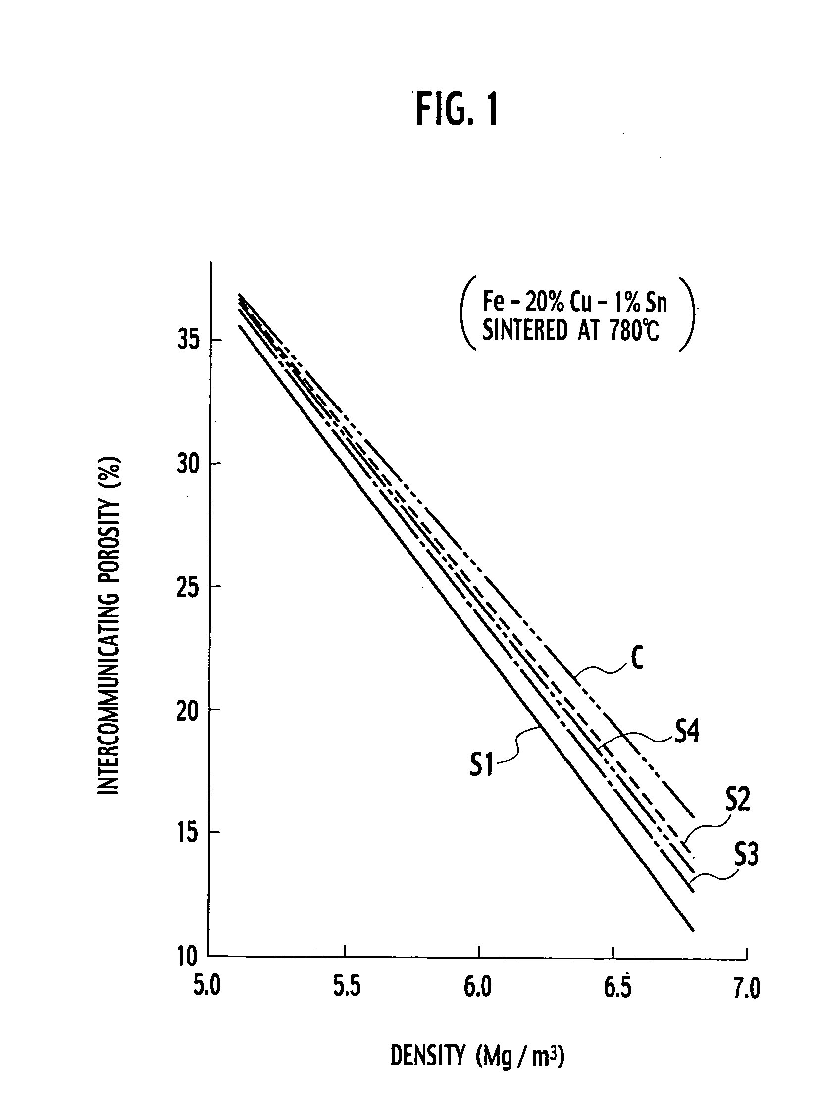
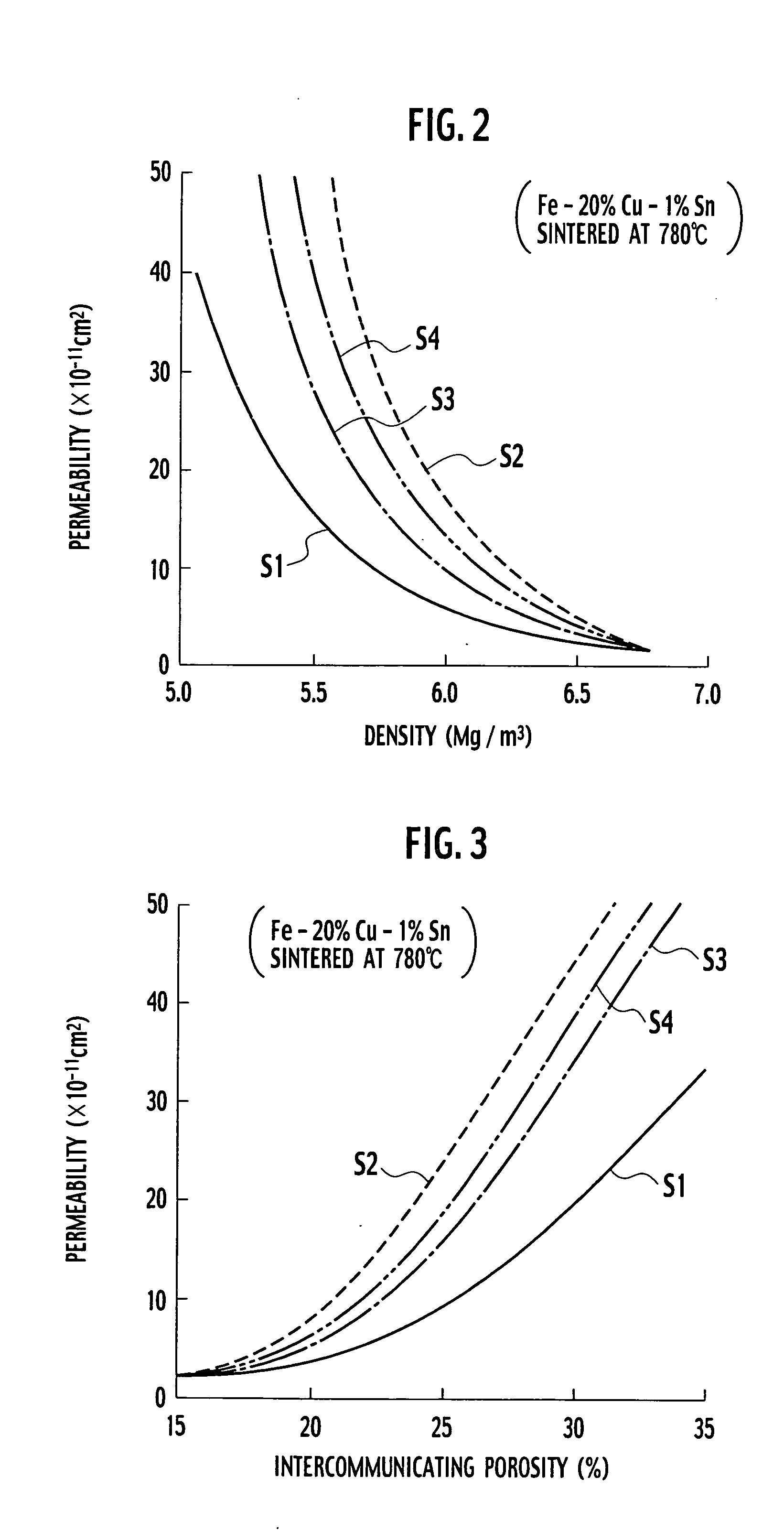
In each of samples S1 to S4, a raw material iron powder, a raw material copper powder and a raw material tin powder were blended and in accordance with the whole composition of 20% Cu, 1% Sn and the balance Fe by mass, and zinc stearate as a powder lubricant was further added to the above powders at a ratio of 0.3% relative to the total mass to prepare a mixed powder. At this time, an electrolyzed copper powder (trade name: CE15) manufactured by Fukuda Metal Foil & Powder Co., Ltd. was used as the raw material copper powder. As the raw material iron powder, a reduced iron powder (trade name: NC100-24) manufactured by Hoganas AB of Sweden and a porous iron powder (trade name: LD80) manufactured by Hoeganas corporation were used, and they were blended at a proportion shown as described below. Sample: Contents of raw material iron powder S1: The porous iron powder of 100% by mass S2: The reduced iron powder of 100% by mass S3: The reduced iron powder of 50% by mass and the porous ...

example 2

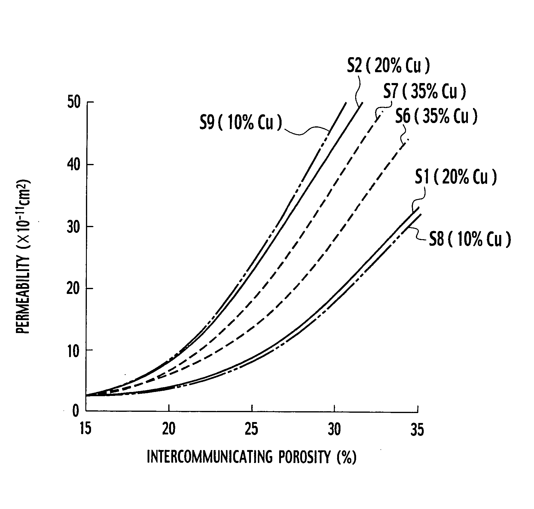
The same operation as that for sample S1 of Example 1 was repeated, excepting that the blending ratios of the raw material powders were changed for shifting the whole composition of the sintered bearing to Fe-35% Cu-1.75% Sn (sample S6) or Fe-10% Cu-0.5% Sn (sample S8), to prepare mixed powders of samples S6 and S8.

Moreover, the same operation as that for sample S2 of Example 1 was repeated, excepting that the blending ratios of the raw material powders was changed for shifting the whole composition of the sintered bearing to Fe-35% Cu-1.75% Sn (sample S7) or Fe-10% Cu-0.5% Sn (sample S9), to prepare mixed powders of samples S7 and S9.

Using each of the above-mentioned mixed powders, a plural number of sintered compacts each having a different density were prepared by every sample in the same manner as in Example 1. The permeability and the intercommunicating porosity were similarly measured. Using the results of measurement, the relationship between the density and the permeabi...

example 3

The same operation as that for sample S1 of Example 1 was repeated, excepting that 25% by mass of the electrolyzed copper powder used as a raw material iron powder was replaced with the same amount of a powder of copper foil (trade name: Cu—S-100) manufactured by Fukuda Metal Foil & Powder Co., Ltd., to prepare a mixed powder. Using this powder, a plural number of sintered compacts having a different density were similarly prepared. The permeability and intercommunicating porosity of each of the sintered compacts were measured and the relationship between the intercommunicating porosity and the permeability of the sintered compacts was prepared. The result is shown in FIG. 9 together with the result of sample 1 of Example 1.

According to FIG. 9, it can be understood that use of the powder of copper foil is effective for decreasing the permeability of the sintered compact. This is considered because the spaces which the copper powder occupies between the iron particles in green com...


PUM

PropertyMeasurementUnit
specific surface areaaaaaaaaaaa
particle sizeaaaaaaaaaa
kinematic viscosityaaaaaaaaaa

Abstract

Disclosed is a manufacturing process of a sintered iron-copper base porous alloy and of an oil-impregnated sintered bearings, having the steps of: preparing a mixed powder comprising an iron powder, and at least one of a copper powder and a copper alloy powder; forming the mixed powder into a green compact; and sintering the green compact to obtain a sintered iron-copper base porous alloy. The iron powder contains a porous iron powder which has a particle size of 177 microns or less and a specific surface area of 110 to 500 m2/kg according to a gas adsorption method. The sintered compact has high intercommunicating porosity and low permeability, and it is sized to prepare the sintered bearing into which a lubricating oil is impregnated.

Description

BACKGROUND OF THE INVENTION 1. Field of the Invention The present invention relates to a process for manufacturing a sintered iron-copper base porous alloy which is used for production of an oil-impregnated sintered bearing applied for various motors, and a process for manufacturing an oil-impregnated sintered bearing. 2. Related Art Many of oil-impregnated iron-base sintered bearings are made of iron-copper base alloy. The iron-copper base alloy includes iron-bronze alloy, iron-brass alloy and alloy further containing another component such as Ni, Co, P, Pb, solid lubricants such as graphite, molybdenum disulfide, and the like. Illustrating a manufacturing process of the iron-bronze base sintered alloy by way of example, a powder of reduced iron or an atomized iron powder is used as a raw material iron powder. And, to this raw material added are an electrolyzed copper powder and a tin powder, or a bronze alloy powder, as a raw material for the bronze alloy phase, and a very sma...

Claims


Application Information

Patent Timeline
Patent Type & Authority Applications(United States)
IPC IPC(8): F16C33/14B22F3/11B22F3/26B22F5/00C22C33/02C22C38/00F16C33/12
CPCC22C33/0207F16C33/104F16C2204/60F16C33/121F16C33/14F16C33/128F16C33/145
Inventor MIYASAKA, MOTOHIRO
Owner HITACHI POWDERED METALS COMPANY
Why Eureka
Try Eureka