Method of producing carbon nanoparticles

a carbon nanoparticle and nanoparticle technology, applied in the direction of carbon cleaning rags, fibre chemical treatment, chemistry apparatus and processes, etc., can solve the problems of failure to produce single-walled nanoparticles, failure to produce carbon nanotubes, fluidised bed methods, etc., to enhance gas-solid mixing and increase reaction efficiency

Inactive Publication Date: 2005-03-24
CAMBRIDGE UNIV TECH SERVICES LTD
View PDF3 Cites 33 Cited by
  • Summary
  • Abstract
  • Description
  • Claims
  • Application Information

AI Technical Summary

Benefits of technology

[0011] A promising process for large-scale synthesis of carbon nanotubes is the fluidised bed method. Fluidised-bed processes are well-established in chemical engineering. Such processes have the advantage of enhancing gas-solid mixing so as to increase reaction efficiency and provide uniform products.

Problems solved by technology

There is often failure to produce carbon nanotubes, and in particular failure to produce single-walled nanotubes [Li and summary of WO 0017102].
Fluidised bed methods also suffer from the disadvantage which applies to the fixed-bed method of failure to produce carbon nanotubes and in particular failure to produce single-walled carbon nanotubes.

Method used


Image

  • Method of producing carbon nanoparticles
  • Method of producing carbon nanoparticles
  • Method of producing carbon nanoparticles

Examples


example 2

[0055] A hot-injection synthesis was conducted using the same supported catalyst of Example 1.

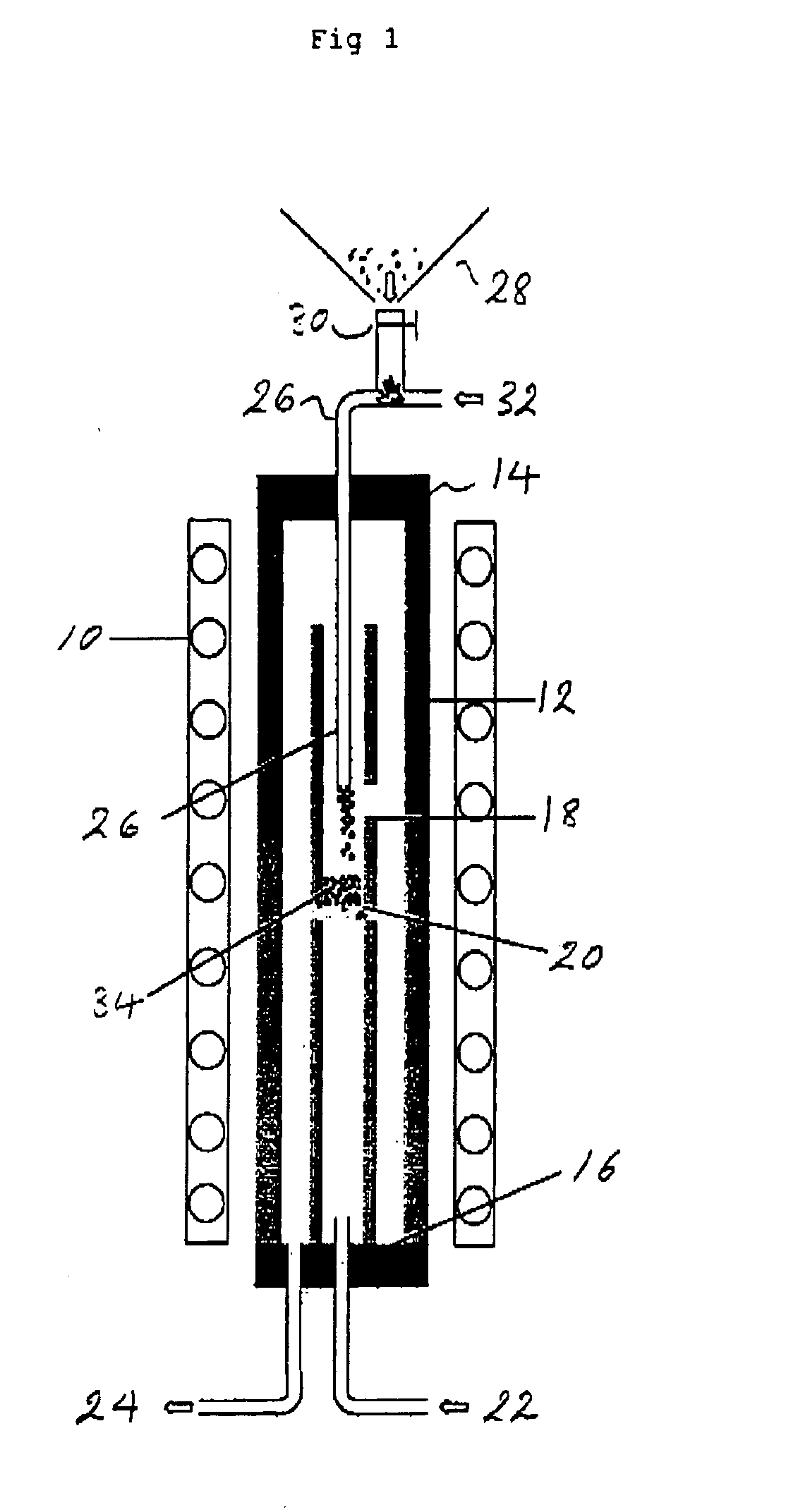
[0056] The supported catalyst was held outside the reactor under an inert argon atmosphere whilst the fluidised bed reactor was heated to 860° C. Once the reactor had reached this temperature, the supported catalyst particles were blown into the top of the vertical reactor using argon (600 ml / min) as the carrier gas.

[0057] During addition of the supported catalyst, a methane-argon mixture (ratio 1:2, 2.0 l / min) was kept flowing through the bed. The catalyst particles were fluidized on the bed in a 1:1 methane-argon mixture, at a flow rate of 2.0 l / min, at 860° C. for 20 min.

[0058] As the catalyst was exposed to the carbon source at the high temperature, an immediate colour change of the catalyst particles from their original green colour to brown or black was observed on those particles which were swept out of the fluidised bed reactor.

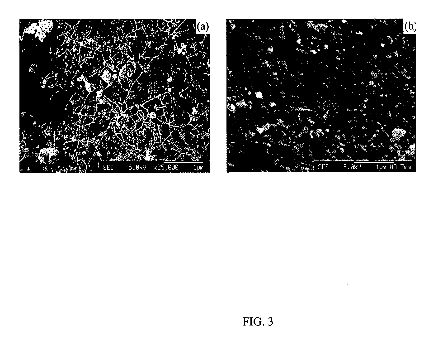
[0059] SEM observation (FIG. 1a)) of the black prod...

example 3

[0060] The supported catalyst injection method of Example 2 was carried out using pure methane rather than a mixture of methane and argon as the injection gas. The synthesis was carried out under the same conditions as Example 2, using 1:1 methane-argon. Multi-walled carbon nanotubes were grown on the surface of the silica-gel particles rather than single-walled nanotubes.

[0061] The advantages of the method of Example 2 include: [0062] 1. The method improves the efficiency of the catalyst, that is, the percentage of catalyst which produces single-walled nanotubes. [0063] 2. The addition and subsequent removal of the catalyst while the reactor is hot means that the plant is run more efficiently than a conventional fluidised bed reactor plant. [0064] 3. The plant can be run in a continuous or semi-continuous mode. A conventional fluidised bed reactor plant is run in a batchwise mode.

[0065] Without wishing to be bound by theory, the applicants believe that good results are achieved i...


PUM

PropertyMeasurementUnit
temperatureaaaaaaaaaa

Abstract

A method of producing carbon nanoparticles comprises the steps of: passing a gaseous carbon source through a heated reactor; and adding catalyst supported on substrate particles or thermally decomposable catalyst precursor supported on substrate particles to the heated reactor to form a fluidised bed; such that carbon nanoparticles are formed in the heated reactor.

Description

FIELD OF THE INVENTION [0001] The present invention relates to a method of producing carbon nanoparticles, and to carbon nanoparticles so produced. BACKGROUND OF THE INVENTION [0002] Carbon nanoparticles may be produced by various routes, including catalytic vapour deposition (CVD), arc discharge and laser ablation. [0003] The CVD route has advantages of low cost and scalability. There has therefore been significant interest in this route. [0004] Typically, in the CVD route, a gaseous carbon source such as a hydrocarbon or carbon monoxide is decomposed by a metallic catalyst in a heated reactor under suitable reaction conditions. Carbon nanoparticles (for example carbon nanotubes) are deposited. [0005] The catalyst may be either supported by a substrate or suspended in the gas stream. The catalyst may be introduced into the reactor in the following ways: [0006] 1. Placing a supported catalyst or catalyst precursor (e.g. ferrocene, iron pentacarbonyl) into the reactor and then introd...

Claims


Application Information

Patent Timeline
Patent Type & Authority Applications(United States)
IPC IPC(8): C01B31/02D01F9/127D01F9/133
CPCB82Y30/00B82Y40/00C01B31/0233D01F9/133C01B2202/06D01F9/127C01B2202/02C01B32/162
Inventor SHAFFER, MILOKINLOCH, IANWINDLE, ALAN H.GENG, JUNFENGJOHNSON, BRIAN F.G.SINGH, CHARANJEETLI, YA-LI
Owner CAMBRIDGE UNIV TECH SERVICES LTD
Why Eureka
Try Eureka