Cell culture vessel for the automated processing of cell cultures

a cell culture and automated processing technology, applied in the field of cell culture vessels, can solve the problems of large impact on the quality and quantity of target protein produced, stability, and non-generally required genes for the production of target proteins, and achieve good fluid flow through the entire vessel

Inactive Publication Date: 2005-03-24
AUTOMATION PARTNERSHIP THE
View PDF7 Cites 68 Cited by
  • Summary
  • Abstract
  • Description
  • Claims
  • Application Information

AI Technical Summary

Benefits of technology

[0012] This configuration overcomes the difference in light paths encountered in U.S. Pat. No. 4,105,415 as the outer profile of the tube is modified by the recessed portions and therefore the light passes through the same thickness of tube material for all readings. It also allows a good fluid flow through the entire vessel.
[0013] Preferably, the tube is of a transparent material, for example, polycarbonate or is at least of a semi-transparent or translucent material, for example, polystyrene so as to allow light to pass through the vessel. The passage of light across the vessel allows for measurement of the OD of the liquid media to be taken externally of the cell culture vessel.
[0014] Preferably, the first light path is a recessed portion of the tube compared to the second light path. The first and second light paths may be recessed and non-recessed portions of the tube respectively. The first light path which is shorter than the second light path allows for the sensitive measurement of OD values when the OD values of the culture in the vessel are at a high level. The second path allows for the sensitive measurement of OD values when the OD values of the culture in the vessel are at a lower level.

Problems solved by technology

A common problem experienced with this method of producing protein is that the genes required for the production of the target proteins are not generally native to the host organism or cells used.
A result of this is that the host organism or cells used may comprise a non-optimal environment for the production, stability, and proper folding of the target protein.
A further problem experienced is that variation in the dynamics of the expression of the target protein, i.e. the rate of production and the point in the growth cycle at which expression is initiated, can have a major impact on the quality and quantity of target protein produced.
Such methods, however, are slow and involve challenging experimental schedules including frequent growth monitoring, which of course is difficult to marry with normal working practices.
Furthermore, there is a limitation to the number of experiments that can be carried out in parallel and variations in operational procedures often occur creating inconsistent and non-reproducible results.
An impact of the labile nature of the desired target proteins is that such variations may substantially affect the quality of the final product.
There is also a health risk to staff when carrying out such large numbers of experiments such as RSI, fatigue, and exposure to genetically modified organisms, for example.
Process steps in the production of protein which have to date made it difficult to carry on its production in a fully automated fashion include measurement of optical density of the bacterial cultures.
However, in conventional culture vessels, a sample of the culture must be removed from the vessel and diluted to get an accurate reading due to the narrow dynamic range of measuring equipment relative to changes in the density of the culture.
This portion is so small and is also right at the bottom of the tube so that it is difficult to access the sediment settling in that compartment whether as a result of settling over time or whether as a result of centrifuging.
Sediment collected in this part of the tube may interfere with the process of light path measurement.
The outer profile of the tube of U.S. Pat. No. 4,105,415 is unaltered by the taper on the internal shape and does not lend itself to injection moulding due to the large changes in wall cross-section because substantial changes in wall thickness cause mould flow problems at the time of moulding.
Also, the relatively thick wall will cause distortion, commonly in the form of sink marks, during cooling from the injection moulding process and therefore adversely affect the optical characteristics of the vessel.

Method used


Image

  • Cell culture vessel for the automated processing of cell cultures
  • Cell culture vessel for the automated processing of cell cultures
  • Cell culture vessel for the automated processing of cell cultures

Examples


Embodiment Construction

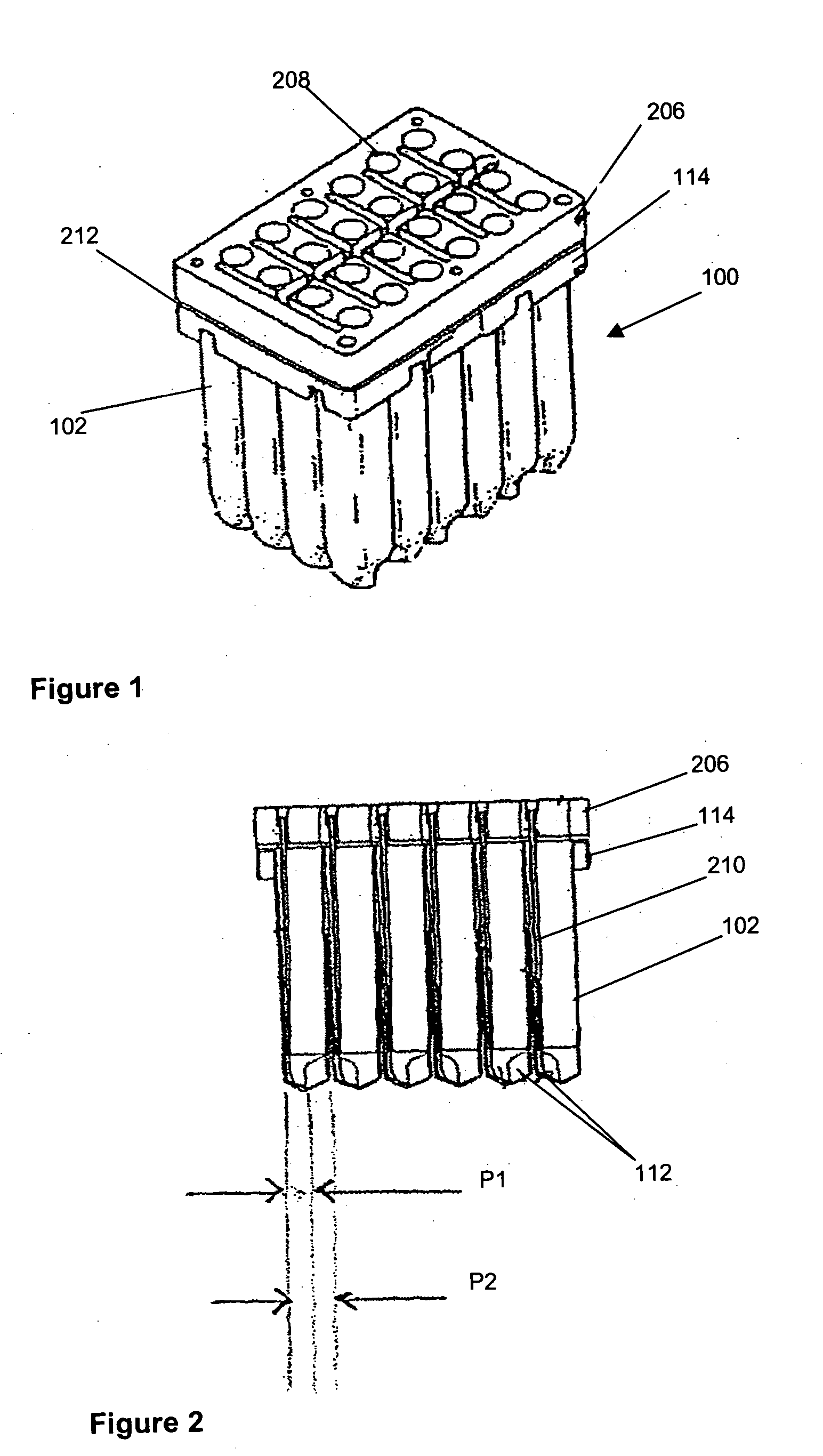
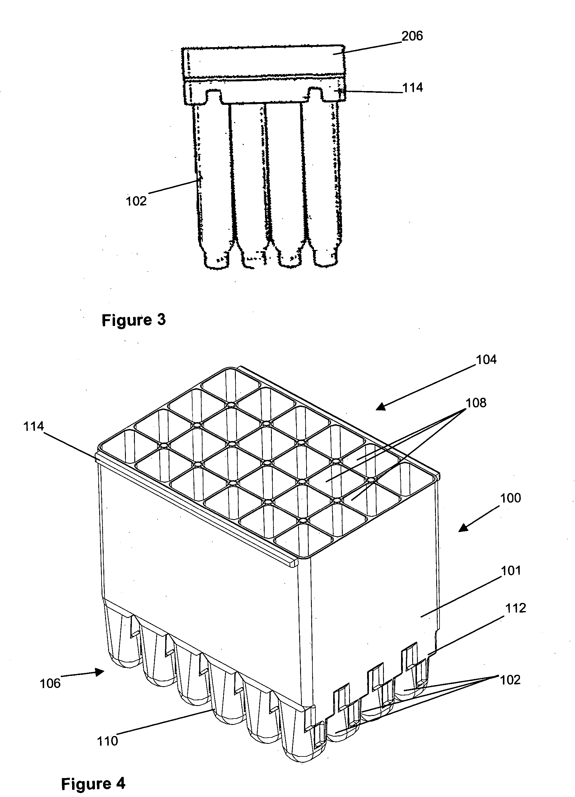
[0029] Referring now to FIGS. 1 to 3 and initially to FIG. 1, there is shown an embodiment of cell culture vessel assembly 100. The cell culture vessel assembly which is formed by injection moulding comprises a substantially rectangular shaped block 101 of 24 identical culture vessels 102 having an open end 104 and a closed end 106.

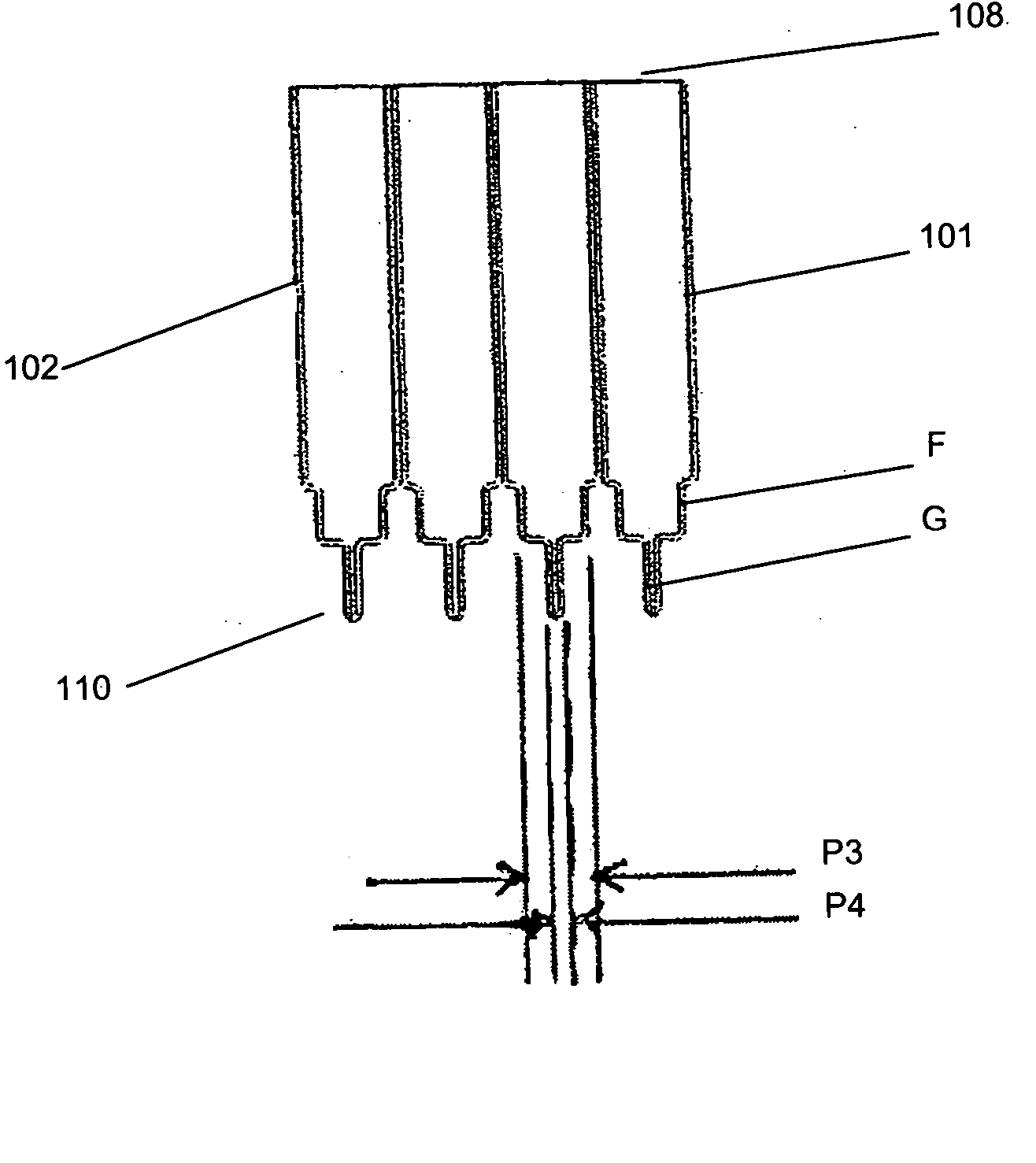
[0030] Each culture vessel 102 is generally in the shape of a rectangular cylinder having an open end 108 and a round closed end 110. The open and closed ends 108, 110 correspond to the open and closed ends 104, 106 of the culture vessel block 101. Each culture vessel 102 has a recessed portion 112 at the closed end 110. The recessed portion 112 generally extends from one side wall of the vessel 102 to midway towards an opposing side wall. This is shown most clearly in FIG. 2. The recessed portion 112 provides a light path length P1 across the culture vessel 102 for sensitive measurement of the OD of the culture when the OD of the culture in the vessel 1...


PUM

PropertyMeasurementUnit
transparentaaaaaaaaaa
optical densityaaaaaaaaaa
physicalaaaaaaaaaa

Abstract

The invention also relates to a cell culture vessel and in particular to a cell culture vessel assembly which aids aeration and allows for reading of the optical density of the culture without removing the culture from the vessel. The cell culture vessel assembly is suitable for use in the production and purification of cell culture products and in particular to the automated production and purification of protein.

Description

BACKGROUND OF THE INVENTION [0001] The present invention relates to a cell culture vessel and in particular to a cell culture vessel assembly which aids aeration and allows for reading of the optical density of the culture without removing the culture from the vessel. The cell culture vessel assembly is suitable for use in the production and purification of cell culture products and in particular to the automated production and purification of protein. [0002] The production and purification of specific proteins from cloned genes are essential first steps in many areas of research and development in the pharmaceutical industry. Generally, the protein of interest (or target protein) is produced within, or secreted by, cultured cells or host organisms and the target protein is recovered from the culture fluid or the cells themselves. More specifically, the gene for the target protein is linked to the appropriate DNA elements controlling transcription and translation in the host organis...

Claims


Application Information

Patent Timeline
Patent Type & Authority Applications(United States)
IPC IPC(8): B01F3/04B01F7/00B01F11/00B01F13/10
CPCB01F3/04531B01F7/00258B01F2215/0037B01F13/1013B01F13/1022B01F11/0085B01F23/233B01F27/1121B01F31/443B01F33/813B01F33/81B01F2101/23
Inventor BARGH, ADRIAN NEIL
Owner AUTOMATION PARTNERSHIP THE
Why Eureka
Try Eureka